Overview
Nuclear facilities require area, process, and effluent radiation monitoring systems (RMS) that continuously measure radiation to ensure safety and meet regulatory requirements. APANTEC, LLC has designed, built, and installed a wide range of RMS for nuclear power plants, accelerators, U.S. national laboratories, government agencies, PET centers, and the U.S. military. The sections below summarize APANTEC's complete RMS, the standard components used to build them, our software solutions, and our services. For more details on any of these capabilities, contact the APANTEC sales department.

Complete RMS
APANTEC RMS are integrated systems that allow real-time, local and remote radiation monitoring across a wide range of environments. Each RMS combines APANTEC-designed detectors, preamplifiers and signal channel analyzers, samplers, assemblies, and software into a complete solution. Custom designs are available — please contact us if you don't see exactly what you need.
- Area Monitors: measure ambient gamma and neutron activity to protect personnel.
- Process and Effluent RMS: monitor critical operating conditions in the reactor or measure effluent values to ensure compliance with regulatory limits.
- PET Center RMS: monitor ambient gamma and neutron activity and airborne radioactive particles at Positron Emission Tomography centers.
- Environmental RMS (ERMS): measure radiation during emergencies, both inside and outside nuclear facilities.
- Tritium Monitoring Systems: measure low-energy airborne alpha/beta activity using gamma-background-compensated flow-through ion chamber detectors.
Standard Instruments
APANTEC has designed several standard instruments that combine and configure to form complete RMS for site-specific needs. This modular approach delivers the flexibility required to meet diverse customer requirements while keeping every system fully documented, tested, and supportable for the long term.
- Detectors: Geiger–Müller (GM), ion chamber, scintillation, and specialized detectors for measurement of gamma, beta, and neutron activity. APANTEC also manufactures the required preamplifiers and signal channel analyzers.
- Display and Control Units
- Samplers and Pumping Systems
Software
It is often desirable to integrate the radiation monitoring channels into a single software database for centralized display, control, and data archiving. APANTEC's DORIS Software Platform provides this capability.
Services
APANTEC offers a full preventive maintenance and repair program for nuclear generating stations using legacy detectors, preamplifiers, and remote/local alarm indicators originally supplied by Nuclear Research Corporation and Canberra. See Maintenance, Repair, & Refurbishment for details.
Complete RMS
Area RMS
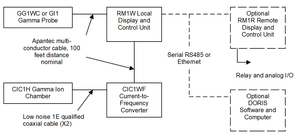
Area RMS continuously monitor ambient gamma and neutron activity using GG1W Gamma GM Detectors, GI1 Ion Chamber Detectors, CIC1H Gamma Ion Chamber Detectors, SD Series Scintillation Detectors, and NB1X/NH1X Neutron Detectors, depending on the field conditions and detector locations. Each channel typically includes a locally mounted detector and a Display and Control Unit (DCU). The local DCU provides on-site annunciation of alarms or channel malfunctions. An optional remote DCU enables off-site operation, and can be replaced by the DORIS software for unified remote control of multiple monitoring channels. A Power-over-Ethernet option allows integration using standard, off-the-shelf components. A typical area radiation monitoring channel is shown below.
Dynamic ranges for Area RMS
| GG1WC-based channel | 10 µR/h to 10,000 R/h |
| GI1-based channel | 100 µR/h to 100 R/h |
| CIC1H-based channel | 2.5×10⁻¹ to 5×10⁷ R/h |
| SD Series–based channel | 1×10⁰ to 1×10⁷ CPM (wide-range optional) |
| NB1X-based channel | 2 µSv/h to 10 mSv/h |
| NH1X-based channel | 10 nSv/h to 100 mSv/h |
Process and Effluent RMS
AM Series Continuous Air Monitors
APANTEC offers an extensive line of continuous air monitors in the AM (Air Monitor) Series. The AM series can be configured to continuously measure beta particulate (P), gamma iodine (I), and/or noble gas (G) activity. Single-, dual-, and three-channel configurations are available to match each application:
| AM1 Series | Single-channel — measures either combined particulate/iodine activity, or noble gas activity. |
| AM2 Series | Dual-channel — measures particulate and iodine separately, or combined particulate/iodine and noble gas. |
| AM3 Series | Three-channel — measures particulate, iodine, and noble gas activity separately. |
The AM series may use the AS43F Fixed Filter Particulate or Iodine Sampler, the AS34M Moving Filter Particulate or Iodine Sampler, and/or the GS45 Noble Gas Sampler.
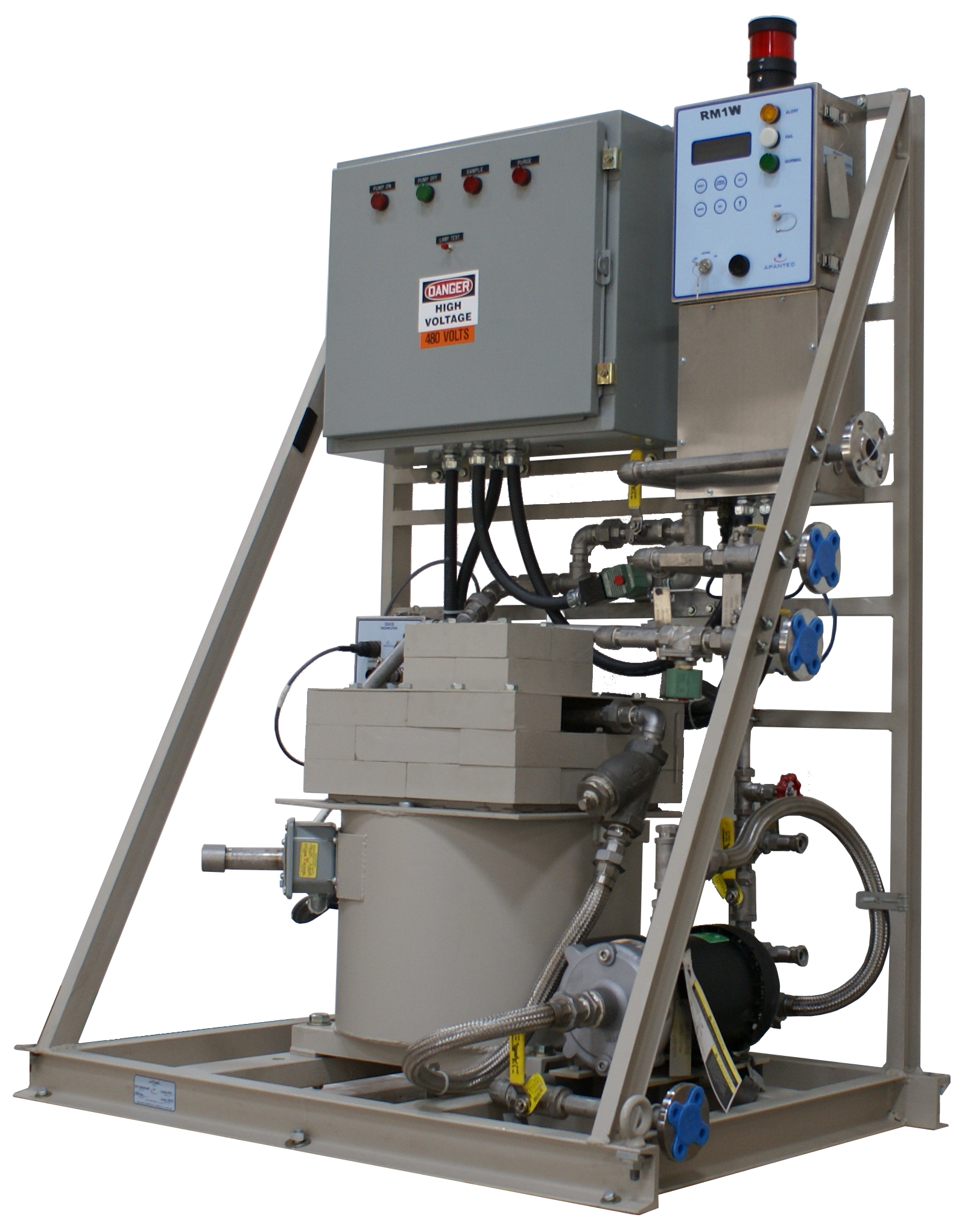
AM1F Continuous Air Monitor — Fixed Filter
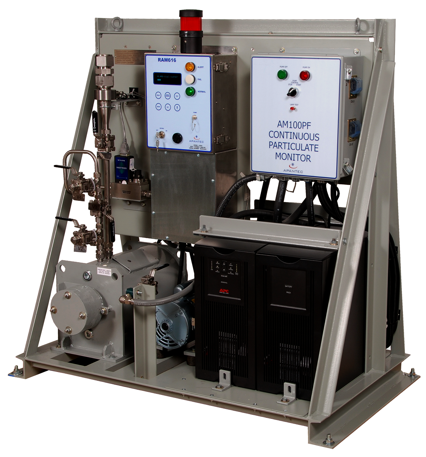
The AM1F is a low-profile fixed-filter monitor that continuously collects and measures radioactive beta particulates or gamma iodines in the sample stream. It can monitor airborne levels in working spaces, or — via process tubing — in remote stacks, ducts, or other air spaces. Representative sampling can be configured if desired.
The sampler uses a fixed-filter geometry with three inches of lead shielding. Inside, an APANTEC SD201P beta scintillation detector provides sensitivity to beta particles, or an SD220N gamma scintillation detector measures iodines. The sampler accepts both a particulate filter paper and an optional activated charcoal cartridge through a common filter holder mechanism. The detector is positioned in a Model AS43F lead shield in close proximity to the sample deposition point.
The detector pairs with an SDA3E preamp/SCA for operation and pulse analysis. The SDA3E output is wired to a locally mounted RM1W Display and Control Unit. The SDA3E preamplifier includes three independent SCA circuits that can be windowed to the beta region of interest. A vacuum pumping system rated for 1 SCFM (30 LPM) is included on the AM1F skid, with local mass flow control to maintain sampling rates as the filter loads. Pump controls are provided on the skid. The local RM1W units interface with an optional remote RM1R unit or DORIS software via serial communications for full remote control. When configured for isokinetic sampling, the skid flow rate is controlled using a velocity signal from the sample point to minimize sample loss during transport to the filter deposition point.
System Features
- System skid assembly, fully wired and plumbed
- AS43F lead-shielded sampler
- SD201P beta scintillation detector or SD220N gamma scintillation detector
- Isotopic check source (optional)
- Fixed filter holder
- Preamplifier / SCA / HV supply
- RM1W Display and Control Unit
- Pump and sample-control (purge) modules
- Power distribution box
← Back to Process and Effluent RMS
AM1G Noble Gas Monitoring System
The AM1G is a single-channel air monitoring system for continuous noble gas measurement. It includes the APANTEC GS45 Noble Gas Sampler for repeatable measurement and attenuation of gamma background energies. The GS45 provides a sensitive volume of approximately five liters surrounded by 4" of lead shielding. An inline particulate-and-iodine fixed filter is provided upstream of the GS45 to keep particulate and iodine activity from interfering with the noble gas measurement. Inside the sampler, mounted in close proximity to the filter media, is an APANTEC SD-series scintillation detector — the preferred choice is the SD201PB beta/gamma scintillation detector.
System Features
- System skid assembly, fully wired and plumbed
- GS45 lead-shielded sampler
- SD201PB beta scintillation detector
- Isotopic check source (optional)
- Fixed filter holder for pre-filtering the sample gases
- Preamplifier / SCA / HV supply
- RM1W Display and Control Unit
- Pump and sample-control (purge) modules
- Power distribution box
The SD201PB pairs with an SDA3E preamp/SCA for operation and signal conditioning. The SDA3E output is wired to a locally mounted RM1W. The detector includes a beta-sensitive plastic scintillator. A vacuum pumping system rated for 1 SCFM (30 LPM) is included on the AM1G skid, along with a flow-control valve and rotameter for setting the desired sample flow. Pump controls are on the skid. The local RM1W units interface with remote RM1W units via serial communications for optional full remote control of each channel.
Noble Gas Activity
| Lower Limit of Detection | 1×10⁻⁷ µCi/cc |
| Dynamic Range | 1×10⁻⁷ to 1×10⁻¹ µCi/cc (referenced to Xe-133) |
← Back to Process and Effluent RMS
AM2IGM Iodine and Noble Gas Monitoring System (Moving Filter)
The AM2IGM is a continuous air monitoring system that measures the iodine and noble gas activity in a sample airstream. It uses two measuring channels arranged in series, with a common vacuum pumping system transporting sample gases through the system. Local RM1R Display and Control Units provide system operation, data concentration, and communications. The iodine channel uses an AS3M lead-shielded moving-filter sampler that collects airborne particulate and iodine on industry-standard charcoal-impregnated filter paper in roll form.
The iodine channel uses a gamma-sensitive scintillation detector (Model SD220N). The SDA3E unit communicates with the skid-mounted RM1R using Ethernet (TCP/IP), RS232, or RS485 to display measured activity and determine alarm states. The exhaust from the iodine channel is plumbed into the inlet of the noble gas monitoring channel. With particulate and iodine activity removed, the sample gases enter the noble gas sampler — a lead-shielded enclosure (Model GS45) with a sensitive volume.
An SD201PB beta scintillation detector inside the sensitive volume measures noble gas activity. It detects nuclear pulses, receives biasing voltage, and transmits count-rate information to the locally mounted SDA3E analyzer.
The noble gas sampler includes a vacuum transducer that automatically corrects measured activity to standard pressure. The vacuum pumping system uses a positive-displacement carbon-vane pump for sample transport. A mass flow meter and proportional control valve allow the sample flow rate to be set manually or matched to a stack/vent velocity for representative sampling. The flow rate feeds into the local RM1R electronics for total-release determination and concentration calculations. Alarms annunciate any low-flow condition.
Iodine Monitors
| Lower Limit of Detection | 1×10⁻¹¹ µCi/cc |
| Dynamic Range | 1×10⁻¹¹ to 1×10⁻⁵ µCi/cc (referenced to I-131) |
Noble Gas Activity
| Lower Limit of Detection | 1×10⁻⁷ µCi/cc |
| Dynamic Range | 1×10⁻⁷ to 1×10⁻¹ µCi/cc (referenced to Xe-133) |
← Back to Process and Effluent RMS
AM31F Continuous Air Monitor — Fixed Filter Particulate, Iodine, and/or Noble Gas
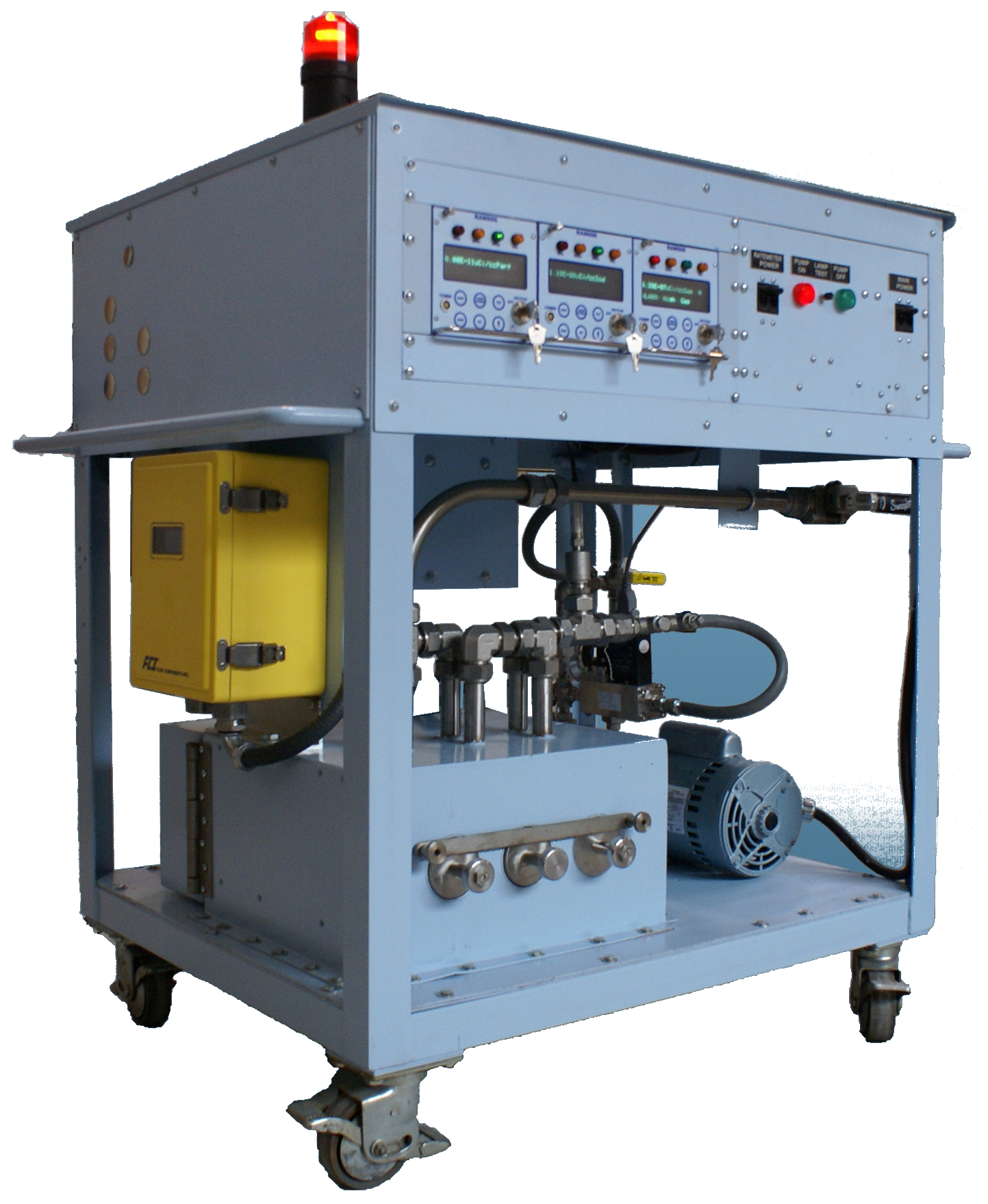
The AM31F is a continuous air monitoring system that measures particulate, iodine, and noble gas activity in a sample airstream. It uses three measuring channels arranged in series within a common lead shield, with a single vacuum pumping system transporting sample gases through the system. Local RM1R Display and Control Units handle system operation, data concentration, and communications.
The particulate channel uses a lead-shielded fixed-filter sampler that collects airborne particles on industry-standard 47 mm filter paper. The deposition geometry provides even distribution and positions the active end of the detector close to the filter for maximum sensitivity. The channel uses a beta-sensitive plastic scintillation detector (Model SD201P), which interfaces with a locally mounted SDA3E spectrum analyzer that supplies low-voltage power, links the detector/SCA with the ratemeter, and provides automatic gain control.
The SDA3E unit communicates with the skid-mounted RM1R using Ethernet (TCP/IP), RS232, or RS485. The exhaust from the particulate channel feeds the iodine monitoring channel, which is similar in construction. In the iodine channel, a TEDA-activated charcoal cartridge or silver zeolite cartridge replaces the particulate filter media. A gamma-sensitive scintillation detector (Model SD220N) sits inside the lead-shielded sampler with its sensitive end exposed to the cartridge. The exhaust then enters the noble gas sampler — a lead-shielded enclosure with a sensitive volume containing either an SD220N gamma or SD201P beta scintillation detector.
The detector signal feeds the SDA3E analyzer. The noble gas sampler includes a vacuum transducer for automatic pressure correction. A positive-displacement carbon-vane vacuum pump transports sample gases, and a flow meter and proportional control valve allow manual flow-rate adjustment.
The AM31F is available in three configurations:
| AM31-1F | Single channel |
| AM31-2F | Two channel |
| AM31-3F | Three channel |
Iodine / Particulate Activity
| Lower Limit of Detection | 1×10⁻¹¹ µCi/cc |
| Dynamic Range | 1×10⁻¹¹ to 1×10⁻⁵ µCi/cc (referenced to Cs-137) |
Noble Gas Activity
| Lower Limit of Detection | 1×10⁻⁷ µCi/cc |
| Dynamic Range | 1×10⁻⁷ to 1×10⁻¹ µCi/cc (referenced to Xe-133) |
← Back to Process and Effluent RMS
AM3PIGF Particulate, Iodine, and Noble Gas Monitoring System (Fixed Filter)
The AM3PIGF is a continuous air monitoring system that measures particulate, iodine, and noble gas activity in a sample airstream using three measuring channels in series. A common vacuum pumping system transports sample gases, and local RM1R Display and Control Units provide system operation, data concentration, and communications. The particulate channel uses a lead-shielded fixed-filter sampler with industry-standard 47 mm filter paper, with deposition geometry tuned to position the detector close to the filter media for maximum sensitivity.
The particulate channel uses a beta-sensitive plastic scintillation detector (Model SD201PB). The detector interfaces with a locally mounted SDA3E pulse analyzer that supplies low-voltage power, provides three independent user-adjustable single-channel-analyzer circuits, and supports automatic gain control.
The SDA3E unit communicates with the skid-mounted RM1R via Ethernet (TCP/IP), RS232, or RS485. The exhaust feeds the iodine channel — also a lead-shielded sampler — where a TEDA-activated charcoal cartridge or silver zeolite cartridge replaces the particulate media, and a gamma-sensitive SD115N detector measures gamma events. The exhaust then enters the noble gas sampler (Model GS45), a lead-shielded enclosure with an SD201PB beta/gamma scintillation detector inside the sensitive volume.
The noble gas sampler includes a vacuum transducer for automatic pressure correction. A positive-displacement carbon-vane vacuum pump transports sample gases, and a mass flow meter with proportional control valve enables either manual flow-rate setting or stack/vent-velocity matching for representative sampling. The flow rate feeds the local RM1R for total-release calculation; alarms annunciate low-flow conditions.
Particulate Activity
| Lower Limit of Detection | 1×10⁻¹¹ µCi/cc |
| Dynamic Range | 1×10⁻¹¹ to 1×10⁻⁵ µCi/cc (referenced to Cs-137) |
Iodine Monitors
| Lower Limit of Detection | 1×10⁻¹¹ µCi/cc |
| Dynamic Range | 1×10⁻¹¹ to 1×10⁻⁵ µCi/cc (referenced to I-131) |
Noble Gas Activity
| Lower Limit of Detection | 1×10⁻⁷ µCi/cc |
| Dynamic Range | 1×10⁻⁷ to 1×10⁻¹ µCi/cc (referenced to Xe-133) |
← Back to Process and Effluent RMS
AM3GFA High-Range Noble Gas Monitoring System
The AM3GFA Accident-Range Noble Gas Monitor measures high-range noble gas activity continuously. It includes parallel particulate/iodine collectors for retention of high-activity particulates and iodine. The P/I filters are lead-shielded to reduce ALARA concerns and are equipped with active gamma monitoring of the accumulated dose — a GG1W gamma GM detector measures the dose rate on each filter media. After the sample gases pass through the parallel collectors, noble gas activity is measured in a lead-shielded sample volume containing a GG1W detector. Detector output communicates with the skid-mounted RM1R via Ethernet (TCP/IP), RS232, or RS485 for activity display and alarm determination.
The noble gas sampler includes a vacuum transducer for automatic pressure correction. Local RM1R units handle system operation, data concentration, and communications. The vacuum pumping system uses a positive-displacement metal-bellows pump, with a mass flow meter and proportional control valve enabling manual flow-rate setting or stack/vent-velocity matching for representative sampling. The flow rate feeds the local RM1R for total-release calculation; alarms annunciate low-flow conditions. The AM3GFA operates in conjunction with the APANTEC AM3PIGM or AM3PIGF normal-range skid to provide seamless monitoring across the entire range. As measured activity rises in the AM3PIGM/F, the AM3GFA accident-range monitor automatically starts its sample pump and begins monitoring; once activity falls, it stops while the AM3PIGM/F resumes normal-range monitoring. The AM3GFA samples at a much lower flow rate to limit high-radioactivity buildup on the particulate and iodine filters.
← Back to Process and Effluent RMS
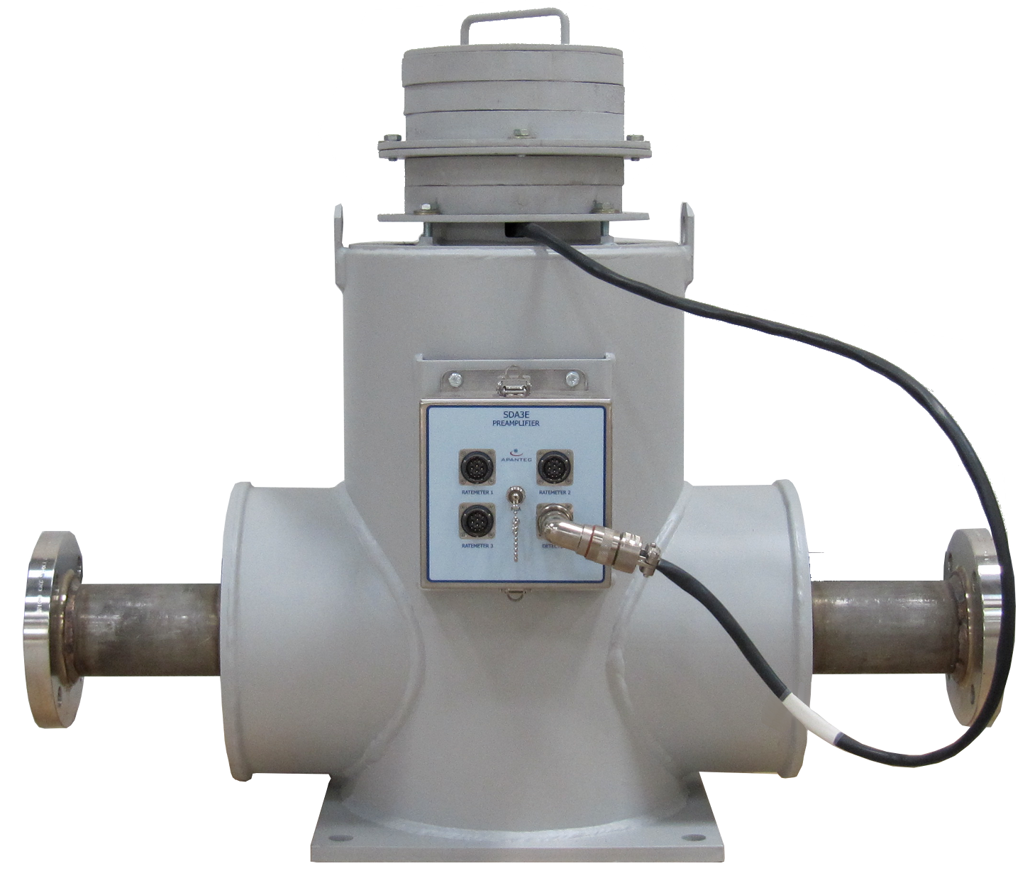
PIM403 Inline RMS
The PIM403 is a process or effluent monitor that continuously measures gamma-emitting isotopes in a sample stream. It is designed for inline monitoring and includes a flange-to-flange sampler for direct process connection.
The PIM403 sampler uses 4" of lead shielding in a 3π geometry, with 150 lb–rated raised-face flanges for mounting on the existing pipe. Inside — accessed via a maintenance port — is an APANTEC SD220N scintillation detector for sensitivity to gamma-emitting isotopes. The detector sits inside a stainless-steel drywell to provide a repeatable measurement geometry. An associated SDA3E preamp/SCA handles detector operation and pulse analysis, with output wired to a locally mounted RM1W Display and Control Unit. The RM1W provides full local display and control of the channel and indicates alarm trips and system malfunctions, with serial communications ports for remote operation. An optional CS-9G isotopic check source mounts on the exterior of the sampler shield for routine operability checks. The maintenance cycle is 24 months, made possible by the absence of moving parts, low-current electronics, and APANTEC's exclusive gain stabilization circuit that automatically compensates for gain shifts caused by temperature changes and aging. APANTEC offers full qualification to the latest nuclear codes and standards, including Class 1E safety applications, performed to IEEE-323, IEEE-344, and Regulatory Guide 1.97.
System Features
- IS4X Inline Sampler
- SD220N Gamma NaI Scintillation Detector Assembly
- SDA3E Preamplifier / SCA / HV Supply
- RM1W Display and Control Unit
- Isotopic check source (optional)
- Lower Limit of Detection: 1×10⁻⁷ µCi/cc
← Back to Process and Effluent RMS
POM403 Online RMS
The POM403 is a process or effluent monitor that continuously measures gamma-emitting isotopes in a sample stream. It is designed for adjacent-to-line monitoring and includes a clamp-on style sampler. The POM403 uses a split-shield design with 4" of lead in a 3π geometry. Inside — accessed via a maintenance port — is an APANTEC SD220N scintillation detector. The detector sits inside a stainless-steel drywell for repeatable measurement geometry. An associated SDA3E preamp/SCA handles detector operation and pulse analysis, with output wired to a locally mounted RM1W. The RM1W provides full local display and control plus serial communications for remote operation. An optional CS-9G isotopic check source mounts on the exterior of the sampler shield for routine operability checks. The 24-month maintenance cycle is enabled by the absence of moving parts, low-current electronics, and APANTEC's exclusive gain stabilization circuit.
APANTEC offers full qualification to the latest nuclear codes and standards, including Class 1E safety applications, per IEEE-323, IEEE-344, and Regulatory Guide 1.97.
System Features
- OS4A Online Sampler
- SD220N Gamma NaI Scintillation Detector Assembly
- SDA3E Preamplifier / SCA / HV Supply
- RM1W Display and Control Unit
- Isotopic check source (optional)
- Lower Limit of Detection: 1×10⁻⁷ µCi/cc
← Back to Process and Effluent RMS
VDM1 Vent/Duct RMS
The APANTEC VDM1 Vent/Duct Monitoring System is designed for direct mounting into the vent or duct to be monitored. Each VDM1 includes a detector mount for inserting the detector into the airstream, an SD201PB beta/gamma scintillation detector, an SDA3E signal analyzer unit, and a locally mounted RM1W. The detector is positioned with its sensitive end inside the vent or duct to measure beta particles. The SD201PB measures both beta noble gas activity and gamma background; the gamma background is then subtracted from the net detector reading to give a true noble gas measurement. Operability checks are performed by pulsing the internal LED in the detector enclosure to produce an upscale indication.
System Features
- SD201PB Beta/Gamma Scintillation Detector Assembly
- SDA3E Preamplifier / SCA / HV Supply
- RM1W Local Display and Control Unit
- MDC: 1×10⁻⁶ µCi/cc, Xe-133
- No vacuum pumping system required for offline measurement
Noble Gas Activity
| Lower Limit of Detection | 1×10⁻⁷ µCi/cc (referenced to Xe-133) |
← Back to Process and Effluent RMS
MSL1 Main Steam Line RMS
The MSL1 is a dual-purpose gamma radiation monitoring system that simultaneously measures noble gases in the steam line and primary-to-secondary leak rate via N-16 in the steam generator. Designed for adjacent-to-line monitoring, it includes a clamp-on shield with 4" of lead in a 3π geometry. The shield can be mounted on the floor adjacent to the steam line or clamped directly to it.
Inside the shield — accessed via a maintenance port — is an APANTEC SD220B scintillation detector. The detector sits inside a stainless-steel drywell for repeatable measurement geometry. The SD220B uses a 2"×2" BGO crystal for increased sensitivity to the high-energy N-16 present in the steam line, and is designed for reliable operation at the elevated temperatures present near a steam line.
A dual-channel SDA3E preamp/SCA handles detector operation and pulse analysis, with output wired to a locally mounted RM1W. The SDA3E supports separate regions of interest for simultaneous noble gas and N-16 measurement, and the detector is temperature-stabilized for high-temperature operation.
The RM1W provides full local and remote display and control of the channel, including alarm and malfunction indication. Serial and Ethernet communication ports enable centralized computer-based control. An optional CS-9G isotopic check source mounts on the sampler shield exterior for routine operability checks.
APANTEC offers full qualification to the latest nuclear codes and standards, including Class 1E safety applications, per IEEE-323, IEEE-344, and Regulatory Guide 1.97.
System Features
- MSL Online Sampler / N-16 Steam Generator Leak Rate Monitor
- SD220B Gamma BGO Scintillation Detector Assembly
- Dual-Channel SDA3E Preamplifier / SCA / HV Supply
- RM1W Digital Display and Control Unit
- Isotopic check source (optional)
- Lower Limit of Detection — Noble gases: 1×10⁻⁷ µCi/cc; N-16: 1×10⁻⁷ µCi/cc
- Detects leaks as low as 0.1 liter per hour
← Back to Process and Effluent RMS
LM1 Liquid RMS
The LM1 monitoring system consists of an SD220N gamma scintillation detector with SDA3E preamp/SCA, a local RM1W, an LS44 liquid sampler, a liquid pumping system, and the cables to interconnect the system electronics. The detector continuously measures gamma energies from the liquid sample stream and feeds nuclear pulses to the preamp/SCA. The preamp/SCA can operate in differentiate mode (measuring a desired region of interest) or integrate mode (measuring gross gamma activity).
The detector/preamplifier electronics also include three user-adjustable single-channel-analyzer circuits for region-of-interest selection. The LM1 achieves a lower limit of detection of 2.7×10⁻⁸ µCi/cc of Cs-137 in a 10 µR/h Cs-137 gamma background, with a 10-minute integration time and two standard deviations of background.
← Back to Process and Effluent RMS
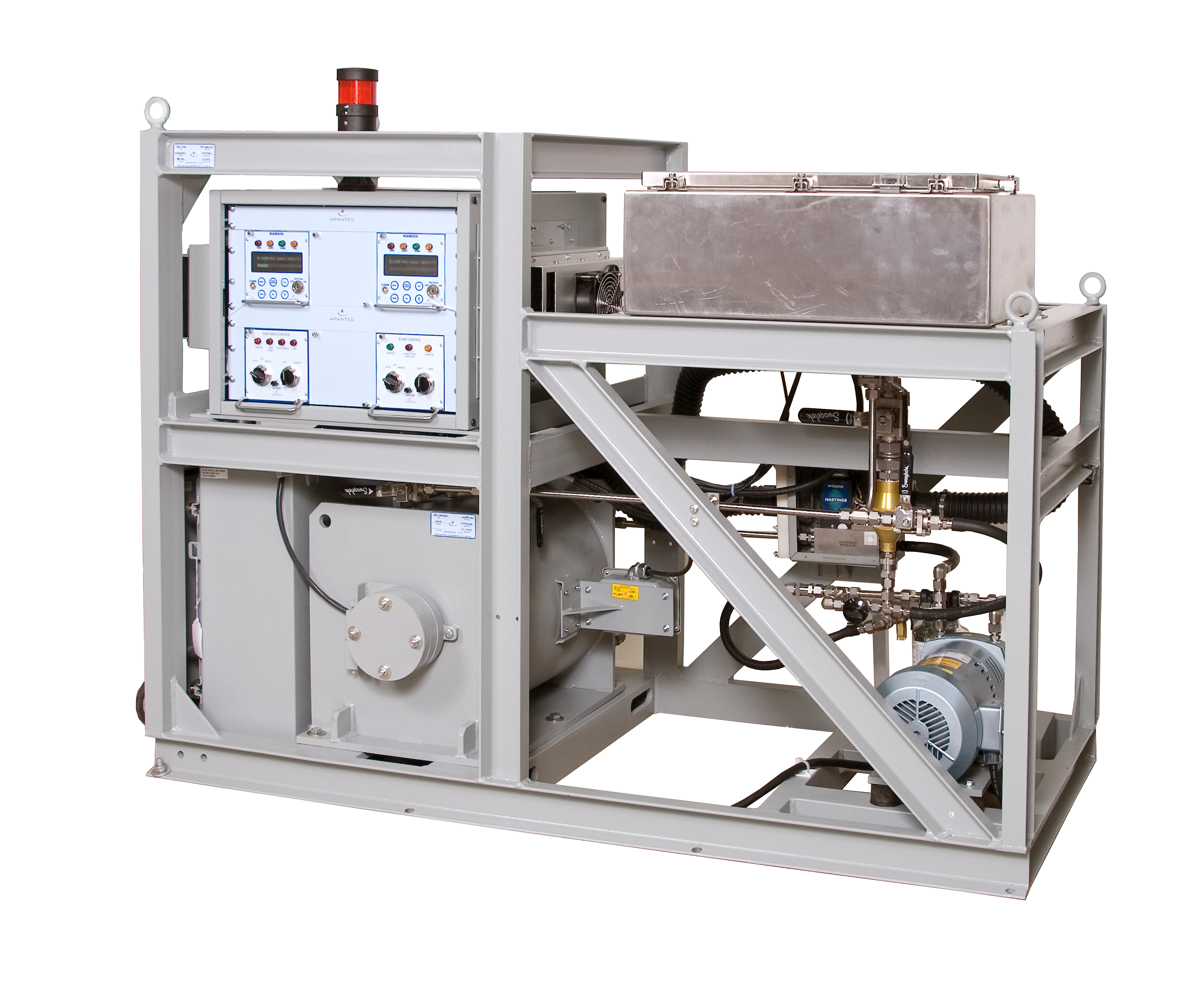
STS200GA Normal/Accident Particulate and Iodine Sampling System
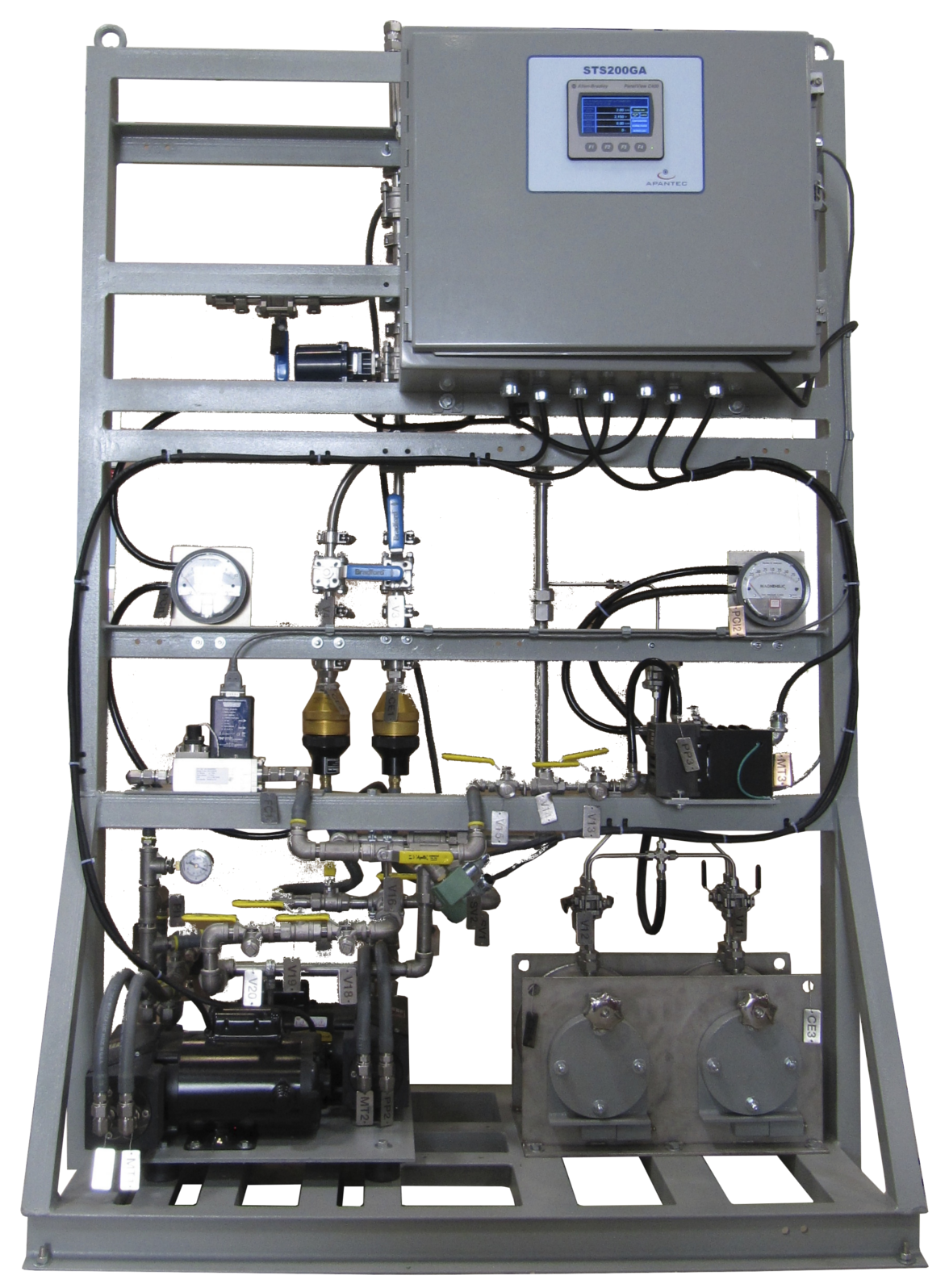
The STS200GA Stack Sampling System is designed to sample particulate, iodine, and noble gas in ventilation exhaust or stack effluent. The system withdraws a measured sample from the stack and transports it through low-loss components to high-efficiency air filters. Stack mass flow rate and sample mass flow rate are accurately tracked and recorded, allowing direct correlation of activity concentration on the filter paper to the stack effluent activity concentration. Parallel flow paths for normal-range P/I filters use redundant vacuum pumps for motive force, with a splitter block (designed per ANSI N13.1-1969) diverting the sample flow to the parallel filter elements. A skid-mounted PLC controller monitors stack and sample flow rates and temperatures, controls system Fail relays, and communicates status to plant personnel.
On notification of an accident condition, the system automatically switches to accident-range sampling. It can also be operated continuously via front-panel controls for manual sampling. A separate flow splitter diverts a portion of the sample to the accident-level filters, with a dedicated vacuum pump providing motive force. The normal-range pump continues to withdraw a representative sample at the normal flow rate (56.6 SLPM), maintaining sampling per ANSI N13.1-1969. The accident-range pump operates at a reduced flow of 1 SLPM to limit contamination from the high particulate/iodine levels expected and to extend filter-exchange intervals.
System Features
- System skid, fully wired, plumbed, and assembled
- Skid-mounted PLC controller
- Two normal- and accident-range particulate/iodine filters
- Normal- and accident-range sample pumps
- Parallel fixed filters
- Compliant with ANSI N13.1-1999
PET Center RMS
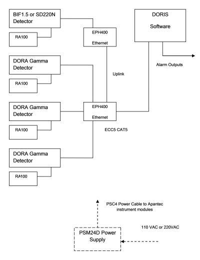
Positron Emission Tomography (PET) centers require monitoring systems for continuous measurement of ambient gamma radiation and airborne radioactive particles. Some PET applications also require monitoring of ambient neutron activity. It is often desirable to integrate the monitoring channels into a single software database for centralized display, control, and data archiving.
APANTEC has designed several standard instruments to meet these requirements. The design philosophy centers on standard modules that can be interconnected and configured to suit site-specific needs. Each APANTEC instrument provides an Ethernet port for ease of installation and flexibility, with standard CAT5 cabling used for interconnection.
Detectors
- DORA Gamma GM Detector
- SD220N Gamma Scintillation Detector
- BIF1.5 Flow-Through Ion Chamber
- NB1X/NH1X Neutron Detector
Display Units
Display and control of the radiation monitoring channels can be accomplished using either discrete microprocessor-based DCUs or a central database software program. Each APANTEC instrument module includes an Ethernet interface, allowing devices to be interconnected with readily available CAT5 cabling.
- RM1 Microprocessor Display and Control Unit
- RA100 Radiation Alarm Module
Detectors
GG1W Gamma GM Detector
The GG1W Intelligent Gamma Probe is an integrated real-time gamma radiation monitoring device that delivers highly accurate ambient gamma readings over a wide range. It uses a halogen-quenched Geiger–Müller tube and a "time-to-count" measurement method that removes the limitations of traditional constant-bias GM tube circuits. The GG1W detects gamma radiation from 80 keV to 2 MeV with ±20% linearity and provides a dynamic range of 10⁻⁴ mSv/h to 10⁵ mSv/h. It connects via a multi-conductor shielded cable to an associated APANTEC Display and Control Unit.
The GG1W is housed in a rugged cylindrical aluminum enclosure with a NEMA 4 rating. APANTEC offers the standard GG1W (wide range), GG1WC (with check source), and GG1WL (low-range version with one GM tube). Each is also available in Sieverts (Sv/h, H*(10)).
GG1W Specifications
| Detector Type | Geiger–Müller tube |
| Range | GG1W, GG1WC: 1×10⁻⁴ mSv/h to 1×10⁵ mSv/h (10 µR/h to 10,000 R/h) GG1WL: 1×10⁻⁴ mSv/h to 100 mSv/h (10 µR/h to 10 R/h) |
| Energy Range | 80 keV to 2 MeV |
| Energy Response | ±20% from 80 keV to 2 MeV (referenced to ¹³⁷Cs) |
| Saturation | Will not saturate in fields up to 10,000 R/h |
| Accuracy | ±15% over entire range |
| Linearity | ±5% |
| Response Time | 4 s |
| Operating Temperature | −31 to 140 °F (−35 to 60 °C) |
| Operating Humidity | 0–95% RH |
| Operating Voltage | 12 VDC, supplied by RM unit |
| Dimensions | 7 in. L × 2.5 in. dia. |
| Weight | 0.9 kg (2 lb) nominal, not including detector mount |
| Check Source | Internal ⁹⁰Sr, 9 µCi, remotely operated, spring return (GG1WC only) |
GG2W High-Sensitivity Gamma GM Detector
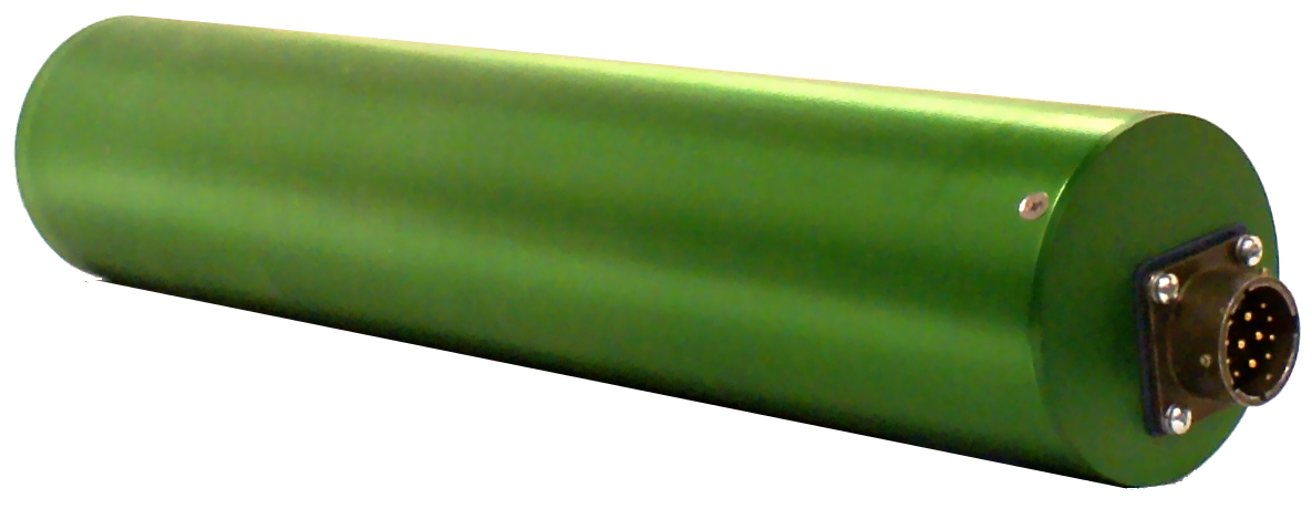
The GG2W Intelligent Gamma Probe is an integrated real-time gamma radiation monitoring device that delivers highly accurate ambient gamma readings over a wide range. It uses a pair of halogen-quenched Geiger–Müller tubes and a "time-to-count" measurement method that removes the limitations of traditional constant-bias GM tube circuits.
The GG2W detects gamma radiation from 50 keV to 3 MeV with ±5% linearity and provides a dynamic range of 1 µR/h to 1,000 R/h. It connects via a multi-conductor shielded cable to an associated APANTEC DCU. The GG2W is housed in a rugged cylindrical aluminum enclosure with a NEMA 4 rating, and is also available in Sieverts (Sv/h, H*(10)).
GG2W Specifications
| Detector Type | Geiger–Müller tube |
| Range | 1 µR/h to 1,000 R/h |
| Energy Range | 50 keV to 3 MeV |
| Energy Response | ±20% from 80 keV to 1.5 MeV (referenced to Cs-137) |
| Saturation | Will not saturate in fields up to 100,000 R/h |
| Accuracy | ±15% over entire range |
| Linearity | ±5% |
| Response Time | 4 s |
| Environment | −31 °F to 140 °F (−35 °C to +60 °C), 0–95% RH |
| Operating Voltage | 12 VDC |
| Dimensions | 12 in. L × 2.5 in. diameter |
| Weight | 2 lb (1 kg) nominal, not including detector mount |
GI1 Ion Chamber Detector
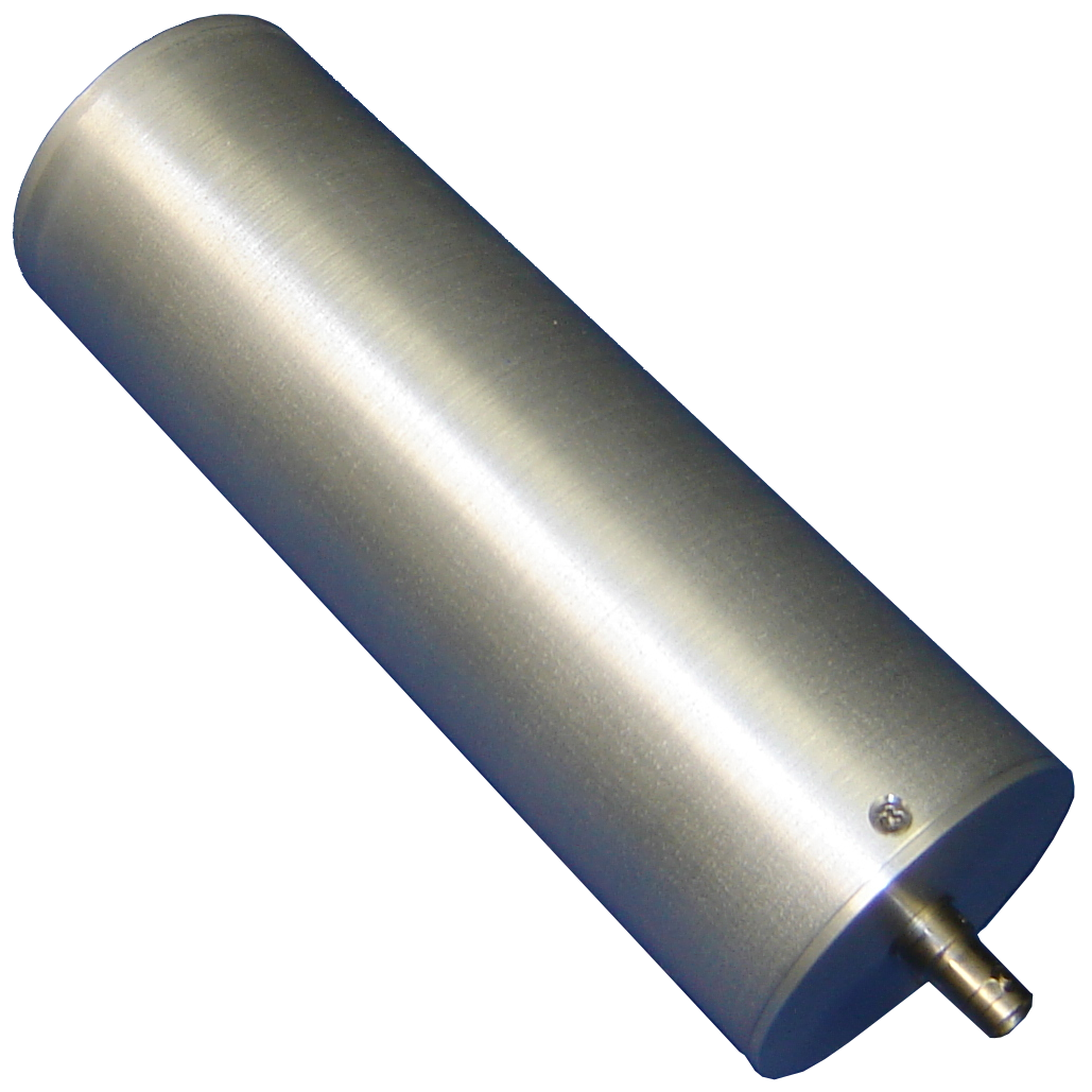
The GI1 ion chamber detector is a sealed ion chamber probe in a cylindrical aluminum enclosure, fitted with a multi-pin circular connector for interconnection to an APANTEC RM1-series DCU. The GI1 is used for area monitoring applications with transient or burst radiation levels, or channels with anticipated high activity such as containment or post-accident detection.
The GI1 includes a current-to-frequency converter that converts the ion chamber output current into pulses for counting by the RM1 input circuitry. The RM1 provides Ethernet and serial RS485 communications for networking with a central computer running APANTEC's DORIS software.
The GI1 measures a range of 100 µR/h to 100 R/h. A version with an internal isotopic check source — designated GI1C — is also available. For high-range and high-TID applications, see the APANTEC CIC1 ion chamber detector.
GI1 Specifications
| Detector Type | Ion chamber, sealed |
| Range | 100 µR/h to 100 R/h |
| Energy Response | ±20% from 80 keV to 2.5 MeV (referenced to Cs-137) |
| Saturation | Will not saturate in fields up to 1,000 R/h |
| Accuracy | ±20% over entire range |
| Operating Temperature | 14 °F to 122 °F (−10 °C to 50 °C) |
| Operating Humidity | 0–95% RH |
| Operating Voltage | 12 VDC, biasing voltages internally generated |
| Dimensions | 12.5 in. (317.5 mm) L × 2.5 in. (63.5 mm) dia. |
| Weight | 3 lb (1.35 kg) nominal |
SD Series Gamma and Beta Scintillation Detectors
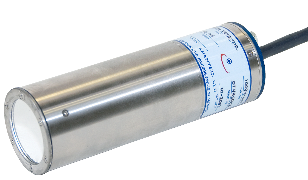
The APANTEC SD-series detectors are scintillation-based radiological detectors used primarily in process and environmental radiation monitoring systems at nuclear power plants. A separate single-channel analyzer (Model SDA3E) handles pulse-height analysis and biasing voltages. The detectors include a gain stabilization circuit for drift-free operation. Each SD-series detector includes a scintillator, photomultiplier tube, mu-metal shield, and dynode chain in a cylindrical enclosure. A light-emitting diode (LED) inside the enclosure supports automatic gain control, and an internal temperature sensor enables temperature compensation. The scintillation material is selected based on process conditions and required sensitivity.
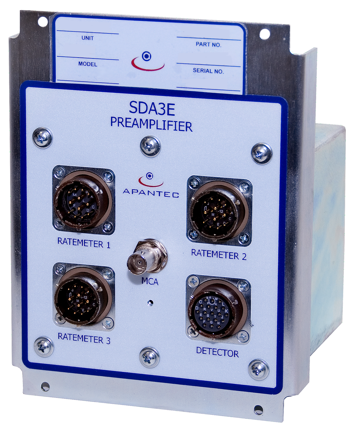
A separate spectrum/analyzer enclosure (Model SDA3E) sits in proximity to the detector and performs several functions. A closed-loop feedback control circuit in the analyzer provides automatic gain stabilization, correcting for variations in gain due to temperature, aging, and power-supply drift. The SDA3E enclosure includes SCA controls and can integrate up to three regions of interest (when used for gamma applications) or operate in gross-counting mode. Software algorithms provide a user-adjustable filter time for integrating count-rate data from each ROI. The SDA3E enclosure is NEMA-4 rated and designed for flat-surface mounting. The detector and SDA3E are connected via a one-meter (nominal) cable, and serial communication links the SDA3E to the remote DCU. All interconnect cables ship fully assembled and tested. Every SD-series detector ships fully calibrated to NIST standards.
Gain-Stabilization Benefits
The SD/SDA series operates with a unique gain-stabilization circuit for temperature-compensated, drift-free operation (< 5% per year), delivering improved accuracy and an 18-month calibration cycle. Inside the detector, an LED is optically coupled to the light-pipe assembly. The LED is pulsed at a known low pulse-repetition rate, with known pulse width and amplitude, to provide a reference signal.
The SDA3E circuitry compares the LED pulses to a reference, providing closed-loop feedback for automatic gain compensation that offsets thermal drift and aging. A thermally compensated LED has distinct advantages over designs based on radioactive seeds. Radioactive-seed scintillation detectors require more expensive crystals and pose disposal challenges when the crystal is no longer usable. Isotope gain shifts are also non-uniform across isotopes, causing measurement inaccuracies. And the statistical nature of the radioactive-seed reference signal does not support low count rates.
SD-Series Features
- "Smart" probe permits rapid deployment
- Automatic gain stabilization for accurate readings and extended calibration cycles
- Mu-metal shield protects against stray magnetic fields
- Sealed cylindrical enclosure for environmental protection
- Optional high-temperature versions for specialized applications
- No radioactive source required (solid-state check source)
- Thermistor for automatic temperature compensation
APANTEC has developed the SD series for use in process monitoring systems. Each SD detector includes a scintillator, photomultiplier tube, mu-metal shield, dynode chain, and Lucite light pipe in a cylindrical enclosure. The LED in the Lucite light pipe supports automatic gain control, and an internal temperature sensor enables temperature compensation. The detector housing is 2.5" in diameter × 7" long. The scintillation material is selected based on the type(s) of radiation to be measured.
An associated preamplifier/analyzer enclosure handles several functions. The preamplifier supplies operating voltage to the scintillation detector. A closed-loop feedback control circuit provides automatic gain stabilization, correcting for variations due to temperature, aging, and power-supply drift. The preamplifier/analyzer enclosure also includes SCA circuitry that can be set for up to three specific regions of interest (gamma applications) or for gross counting mode.
An optional MCA with a full 1024-channel gamma spectrum is available for more detailed analysis. The preamplifier/analyzer enclosure is NEMA-4 rated and mounts to a flat surface. The detector connects to the preamplifier/analyzer via a four-foot (nominal) cable, and Ethernet links the analyzer to the local DCU. All interconnect cables ship fully assembled and tested.
Extended-range scintillation detectors are also available. These use the APANTEC process to measure detector output current in high fields, automatically switching from pulse-counting mode to current mode.
The SD220N detector consists of a gamma-sensitive 2"×2" NaI crystal optically coupled to a photomultiplier (PM) tube. A reference LED and temperature sensor are included for gain stabilization. The SD220N's gain-stabilization circuitry provides temperature-compensated, drift-free operation for improved accuracy and extended calibration cycles. The detector pairs with an external analyzer that interfaces it with the DCU. A mu-metal shield surrounds the PM tube to protect it from gain changes due to stray magnetic fields or orientation changes relative to Earth's magnetic field. The full assembly is housed in a moisture-proof stainless-steel enclosure with a multi-pin circular connector for electrical interconnection.
APANTEC also offers the SD201PB beta scintillation detector for monitoring beta activity. The SD201PB is similar in construction to the SD220N but replaces the gamma-sensitive NaI crystal with a thin NE102 plastic scintillator. The detectors operate in conjunction with an SDA3E analyzer unit, which takes power from the ratemeter and supplies the low- and high-voltage power required for detector operation. The SDA3E also drives the LED, reads the temperature sensor, compares the LED signal from the PM tube against a temperature-compensated reference, and generates a correction voltage to automatically adjust the high voltage and stabilize gain.
SD-Series Detector Configurations *
| Model | Crystal | Size | Radiation Measured | Temperature |
|---|---|---|---|---|
| SD115N | NaI | 1" × 1.5" | Gamma | −10 °C to +50 °C |
| SD220N | NaI | 2" × 2" | Gamma | −10 °C to +50 °C |
| SD115NH | NaI | 1" × 1.5" | Gamma | −10 °C to +90 °C |
| SD220BH | BGO | 2" × 2" | Gamma | −10 °C to +150 °C |
| SD201PB | NE102 | 2" × 0.01" | Beta | −10 °C to +50 °C |
| — | BGO | ¼" cube | Gamma | −10 °C to +50 °C |
* Other crystal sizes, crystal combinations, temperature ratings, and extended-range detectors are available — please contact the factory.
SD220N Gamma Scintillation Detector Specifications
| Sensor | 2" × 2" NaI crystal |
| Detector Output | Analog negative pulse |
| Detector Accuracy | ±15% of true field intensity |
| Detector Linearity | ±5% |
| Operating Temperature | 14 to 122 °F (−10 to 60 °C) |
| Operating Voltage | 450 to 1500 V |
| Nominal LED Background | 10–15 CPM |
| Operating Humidity | 0–95%, non-condensing |
| Housing | Moisture-proof stainless steel, 2.7 kg (5 lb) |
SD201PB Beta Scintillation Detector Specifications
| Sensor | Beta, NE102 plastic (2" dia. × 0.01" thick) |
| Detector Output | Negative pulse |
| Detector Accuracy | ±15% of true field intensity |
| Detector Linearity | ±5% |
| Operating Temperature | 14 to 149 °F (−10 to 65 °C) |
| Operating Voltage | 500 to 1500 V |
| Nominal LED Background | 10–15 CPM |
| Operating Humidity | 0–95%, non-condensing |
| Housing | Moisture-proof stainless steel, 2.7 kg (5 lb) |
SDA3E Preamplifier/SCA Specifications
| Input Impedance | 9.1 kΩ |
| Voltage Gain | 16 |
| Output Signal | Approx. 1 mV per keV |
| Operating Temperature | 14 to 122 °F (−10 to 50 °C) |
| Energy Low Range | 50 keV to 2.55 MeV |
| Energy High Range | 1.5 MeV to 7.5 MeV |
| Housing | NEMA-4X stainless-steel box |
| Size | 152.4 × 152.4 × 101.6 mm (6 × 6 × 4 in.), 2.2 kg (4 lb) |
| Power | ±12 V |
| Placement from Detector | Up to 5 m (15 ft) |
| Placement to Ratemeter | Up to 293 m (~1,000 ft) |
| SCA Channels | 3 |
CIC1H Gamma Ion Chamber Detector
↓ CIC1H Datasheet ↓ CIC1F Current-to-Frequency Datasheet
The CIC1H ion chamber detector is a sealed ion chamber probe in a cylindrical stainless-steel enclosure, with two coaxial connectors that interface with an associated CIC1F current-to-frequency converter. The CIC1F converts the ion chamber output current into TTL-level pulses suitable for counting by an APANTEC RM-series DCU. The CIC1H is used on channels with anticipated high activity such as containment or post-accident detection, and is qualified for operation in LOCA accident-level conditions. The associated RM provides Ethernet and serial RS485 communications for networking with a central computer running APANTEC's DORIS software. The CIC1H measures a range of 2.5×10⁻¹ to 5×10⁷ R/h.
CIC1H Specifications
| Detector Type | Ion chamber, sealed |
| Range | 2.5×10⁻¹ to 5×10⁷ R/h |
| Energy Response | ±30% from 80 keV to 2.5 MeV (referenced to ¹³⁷Cs) |
| Accuracy | ±40% over entire range |
| Operating Temperature | 14 to 375 °F (−10 to 191 °C) |
| Operating Humidity | Up to 100% RH |
| Operating Voltage | 1500 VDC maximum, supplied by CIC1F |
| Dimensions | 13.6 in. L × 3 in. dia. |
| Weight | 3 lb (1.35 kg) nominal |
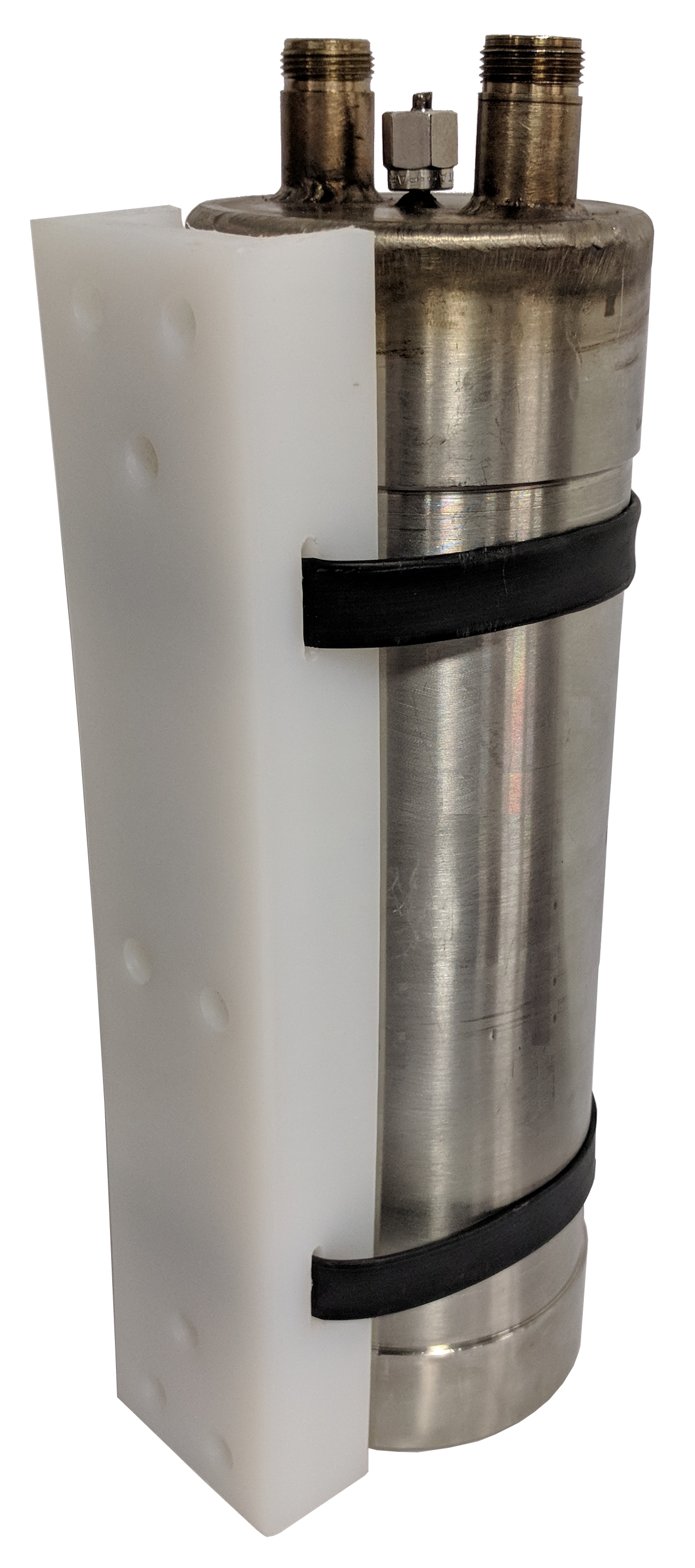
NB1X / NH1X Series Neutron Detector
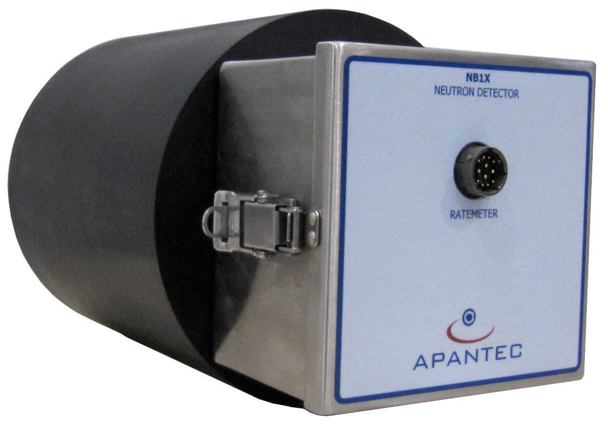
The APANTEC neutron probe is based on the design by I. O. Andersson and J. Braun and provides a dose response corresponding to the human body. It directly measures the biological dose rate of neutrons across energies from thermal (0.025 eV) to 15 MeV. The probe contains a proportional counter that produces pulses from neutron interactions. The proportional counter is essentially a thermal neutron detector, but the probe as a whole responds to thermal, epithermal, and fast neutrons. A high-hydrogen-content polyethylene moderator attenuates and moderates incoming neutrons so the net flux at the proportional counter is a thermal/low-epithermal flux representative of tissue-equivalent dose rate. The proportional counter is also enclosed in a tissue-equivalent boron-impregnated sleeve, which mediates the neutron–counter interaction. The NB1X/NH1X provides a pulse output to an associated RM-series DCU, which in turn provides serial RS485 and Ethernet communications for networking with a central computer running APANTEC's DORIS software. The NB1X/NH1X is available in the configurations below.
NB1X / NH1X Specifications
| Detector Type | NB1X: BF₃ counter with boron-impregnated sleeve and polyethylene moderator NH1X: He-3 counter with boron-impregnated sleeve and polyethylene moderator |
| Range | 0.1 µSv/h to 100 mSv/h |
| Energy Range | 0.025 eV to 15 MeV |
| Energy Response | ±20% from 0.025 eV to 15 MeV |
| Accuracy | ±15% over entire range |
| Linearity | ±5% |
| Response Time | 4 s |
| Operating Temperature | −31 to 140 °F (−35 to +60 °C) |
| Operating Humidity | 0–95% RH |
| Operating Voltage | +12 VDC, biasing voltage supplied by RM unit |
| Dimensions | 12 in. (304.8 mm) L × 8 in. (203.2 mm) dia. |
| Weight | 20 lb (9 kg) nominal |
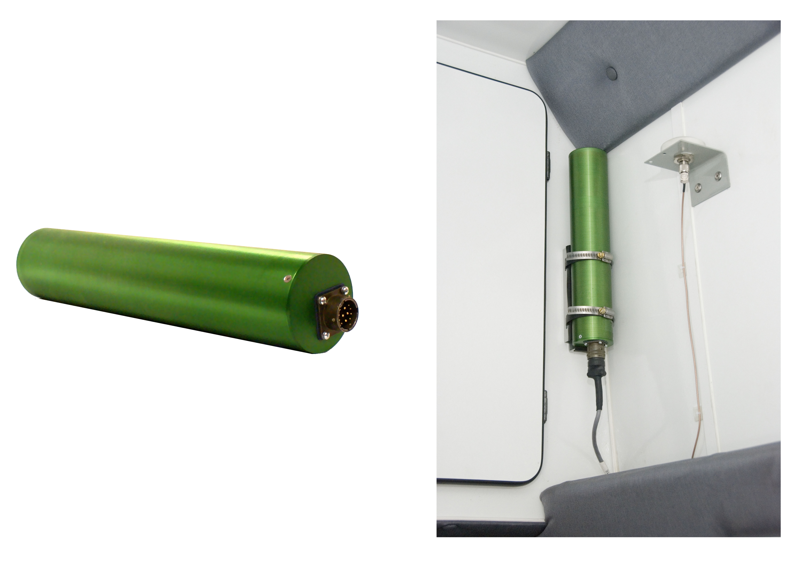
DORA Gamma GM Detector
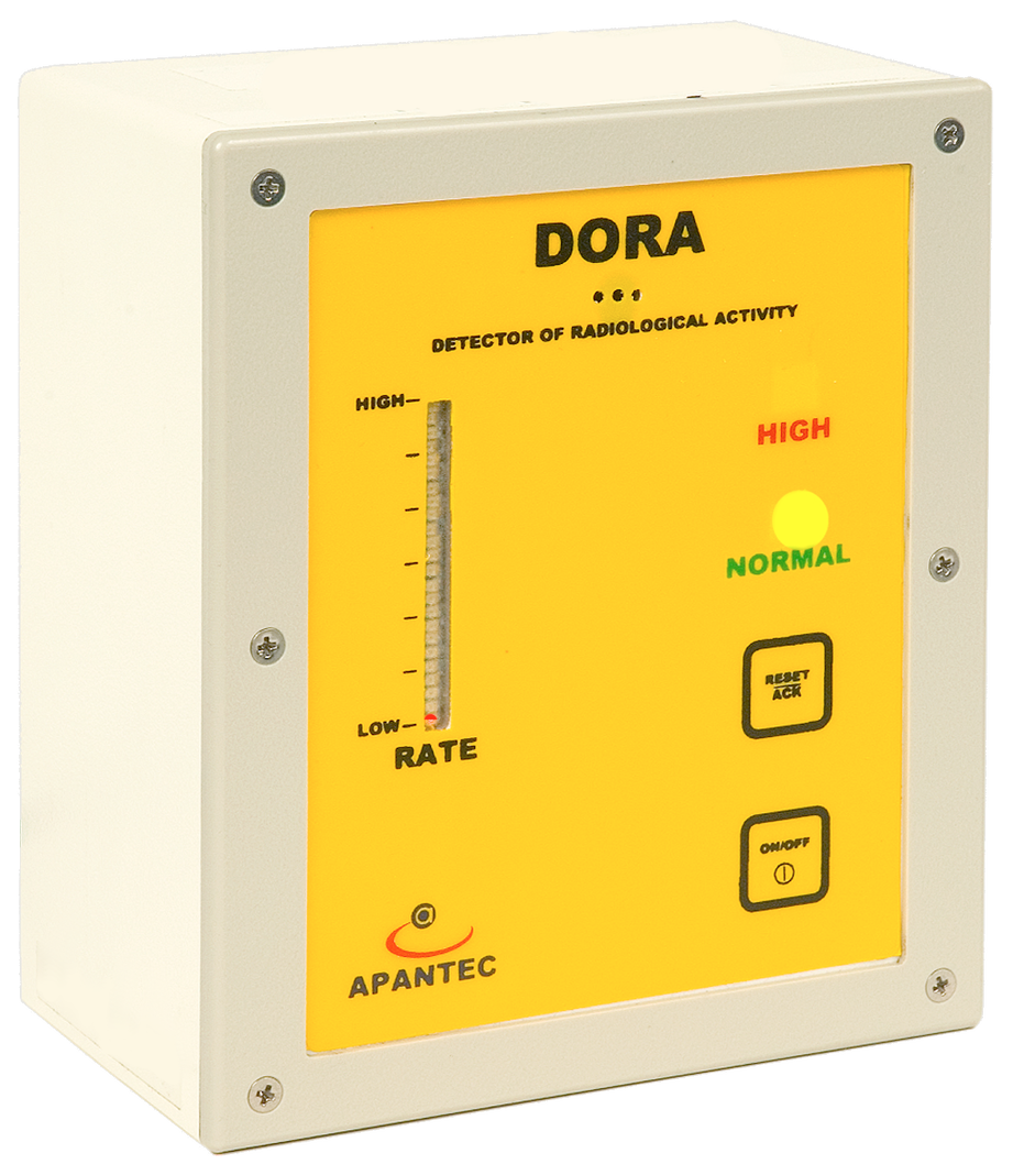
DORA is an integrated real-time gamma radiation monitoring device that delivers highly accurate ambient gamma readings over a wide range. It provides normal/high radiation indication locally, and reports comprehensive rate, dose, and status information to a remote computer or DCU over a high-speed Ethernet TCP/IP network. DORA is built around a high-speed microprocessor that handles all measurement, indication, communication, and historical record retention. The microprocessor system integrates program FLASH memory for firmware, high-speed SRAM for program execution, battery-backed SRAM for short-term history, an xD memory card for expanded long-term history, a real-time clock (RTC), an Ethernet interface, and serial communications ports for the RS485 and USB interfaces. The RS485 port is an alternate interface to Ethernet for remote data access. The USB port is used only for configuration changes and firmware upgrades.
The radiation measurement system is built around a halogen-quenched GM tube, high-voltage supply, and time-to-count driver. The 1"-diameter by 2"-long GM tube — with energy-compensation shielding — provides a nominal sensitivity of 1700 CPM per mR/h. The GM tube and time-to-count control techniques deliver accurate, highly linear operation from a 10 µR/h background up to 10 R/h.
APANTEC also offers an extended-range version of DORA that uses two GM sensors inside the enclosure. This version measures a dynamic range of 10 µR/h to 10,000 R/h. The energy-compensation shield provides uniform energy response from 80 keV to 2.5 MeV. The high-voltage power supply for GM tube bias is generated internally. An H*(10) Sievert response is also available, covering a range of 0.1 µSv/h to 100 Sv/h.
Dose rate, integrated dose, and status information are available over TCP/IP Ethernet or RS485. An analog output is available for dose-rate indication, programmable across the dynamic range as a 0–10 VDC signal.
Radiation trend is shown on a trend bar. Two LEDs (green for Normal, red for High Alarm), an audible alarm, and a relay contact for an external indicator communicate status. The audible alarm can be muted while the alarm condition still exists by pressing the reset/ack button. The relay provides a contact closure on high alarm; the contacts are isolated from the rest of the probe's circuitry and may be used to control an external annunciator.
DORA is also adaptable to process radiation measurement via an integrated analog input that allows monitoring of external process variables such as temperature, flow, or pressure.
DORA is housed in a NEMA 12 enclosure for wall mounting, supporting use across a wide variety of environments without impacting operation or accuracy. An external "smart" probe port allows expandability and detection of radiation in a broad range of applications. A wide variety of external smart probes for measuring alpha, beta, gamma, and neutrons are available.
DORA Specifications
| Detector | Halogen-quenched, energy-compensated GM tube |
| Sensitivity | 1700 CPM/(mR/h) |
| Range | 10 µR/h to 10 R/h |
| Indicators | Alarm: red Normal: green Audible: 80 dB @ 3 ft |
| Outputs | Digital: (1) TCP/IP Ethernet, (1) RS485 serial Analog: (1) 0–10 VDC Alarm Relay: 150 mA @ 120 VAC, 150 mA @ 28 VDC |
| Inputs | 0–5 VDC analog input |
| Power | 12 VDC, 0.5 A nominal (9 to 15 VDC); optional 110/220 VAC, 50/60 Hz converter |
| Operating Temperature | −4 to 122 °F (−20 to 50 °C) |
| Operating Humidity | 0–95% RH, non-condensing |
| Dimensions | 5" H × 4" W × 3" D |
| Weight | 2 lb (0.9 kg) |
Display and Control Units
Display and control of radiation monitoring channels can be accomplished using either discrete RM-series microprocessor-based DCUs or the DORIS central database software. Each APANTEC instrument module includes an Ethernet interface for interconnection via standard CAT5 cable.
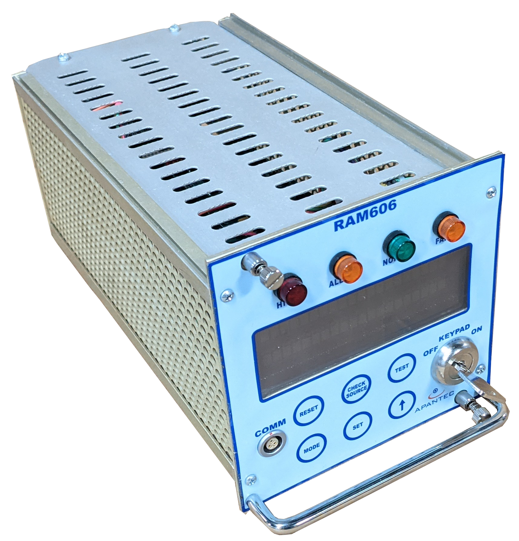
RM1R / RM1W Display and Control Unit
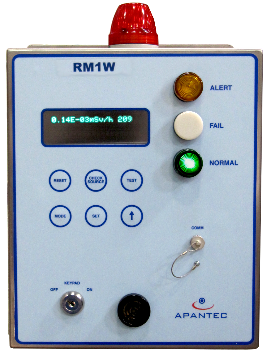
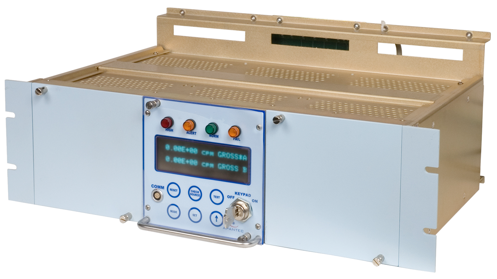
The RM Radiological Activity Monitor series instruments are distributed display and control units with multi-function capabilities. They use a 32-bit ARM-based microcontroller that handles three timer/counter acquisition channels, the user interface (display, keypad, indicators), analog I/O, digital I/O, and robust communications including RS232, RS485, and optional TCP/IP Ethernet for networking. Digital and analog I/O circuitry allows the RM units to operate as data concentrators and controllers for external devices. The RM design has three radiological counting channels, allowing simultaneous processing of data from up to three smart-sensor channels.
Information is displayed on a 2-line × 20-character vacuum fluorescent display on the front panel. The RM also provides discrete indicators for instrument status — High and Alert radiation alarms, Fail/Malfunction, and Normal — plus an audible sounder for alarm annunciation on the RM1W wall-mounted units. Two packaging arrangements are available: the RM1W in a NEMA-12 wall-mount enclosure, typically used as the local DCU; and the RM1R in a chassis-mount configuration, typically used as the remote control-room DCU. Both are functionally equivalent and share common circuit-board designs. Operators interact with the RM via a keypad protected by a key-lock switch and/or password. The keypad sets and views alarms, configures detector parameters, acknowledges alarms, operates the check source, and performs administrative functions such as setting channel identification.
When used with process or effluent channels, the RM acts as a data concentrator and processor, integrating external signals such as flow rate and pressure into the radiological measurement. Analog signals enter the microprocessor via 16-bit ADCs — five ADC circuits are included for external sensors. The RM also accepts up to six digital input signals for external digital devices, often used for applications such as normal/accident-range noble gas monitoring, where a digital signal triggers automatic switchover. Outputs include three RS485 ports (or optionally two Ethernet Modbus-over-TCP/IP ports), one RS232 port, four 4–20 mADC or 0–10 VDC analog outputs, eight digital outputs, and five DPDT (2-form-C) and one SPDT (1-form-C) relays. Relays are factory-programmed for customized configuration — typically high alarm, warning alarm, fail conditions, check-source activation, and miscellaneous alarms such as low-flow. Analog outputs are scaled to the channel's dynamic range via a 16-bit DAC and are optically isolated.
The RS485 ports and Ethernet TCP/IP port enable networking with database software or other DCUs. The RS232 port on the front panel provides easy access for portable-device configuration. RM units operate from 24 VDC, supplied by an AC-to-DC converter that accepts universal AC input from 90 to 260 VAC, 47 to 63 Hz, single-phase. The power supply is UL- and CE-certified and filtered against dropouts, voltage variations, surges, and spikes. Critical operating parameters are stored in non-volatile EEPROM so the system recovers from power outages without operator intervention. Historical data is retained in battery-backed non-volatile memory for up to 100 hours after loss of primary power. Operating parameters are field-configurable, allowing a common platform across multi-function channel and display configurations.
The RM-series ratemeters are qualified for seismic, EMI/RFI, and environmental conditions per the latest nuclear-industry standards.
RM1R / RM1W Specifications
| Processor | 32-bit high-performance ARM-based integrated microcontroller — three integrated timer/counter channels for data acquisition, four UARTs for serial communications, digital I/O, watchdog timer, battery-backed RAM, program FLASH, real-time clock |
| Display | 2 × 20-character vacuum fluorescent display |
| Alarm/Status Indicators | Red: HIGH Amber: ALERT White: FAIL Green: NORMAL Audible alarm (RM1W only) |
| Outputs | Digital: (1) RS232, (3) RS485, optionally (2) Ethernet Analog: (4) 0–10 VDC, or (4) 4–20 mADC isolated Relays: (6) DPDT and (1) SPDT for FAIL, ALERT, HIGH, and other alarms (5 A @ 115 VAC resistive) |
| Power | 90–260 VAC, single phase, 47 to 63 Hz, 15 W |
| Operating Temperature | 14 to 122 °F (−10 to 50 °C) |
| Operating Humidity | 0–95% RH, non-condensing |
RA100 Radiation Alarm Module
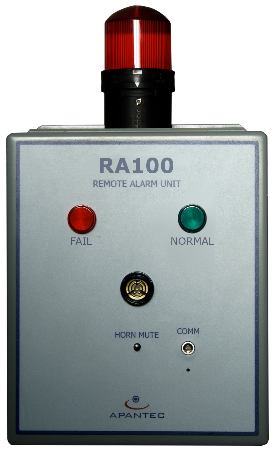
The RA100 is used for remote annunciation of alarm status from an associated RM1 DCU. It is often desirable to provide an alarm indication at a location away from the DCU to protect personnel from elevated radiation. The RA100 includes indicators for High radiation, Alert radiation, and Fail conditions: a red indicator illuminates when activity exceeds the High alarm setpoint, a yellow indicator illuminates at the Alert setpoint, and a white indicator illuminates on a channel malfunction. An audible alarm provides annunciation on a High alarm. The RA100 includes an Ethernet interface for connection to an associated RM1 DCU or DORIS database software. It is housed in a NEMA-4 wall-mounted enclosure and operates from 0 °C to 60 °C and 0–98% RH (non-condensing).
Features
- Power and control from any RM1-series or DORA-I ratemeter
- Stainless-steel enclosure
- Dust-proof and splash-proof
- Wall-mountable
- Long-life, bright LEDs for visual display
- Continuous sounder
- Highly customizable for any application
DORA-I Intelligent Radiological Display and Control Unit
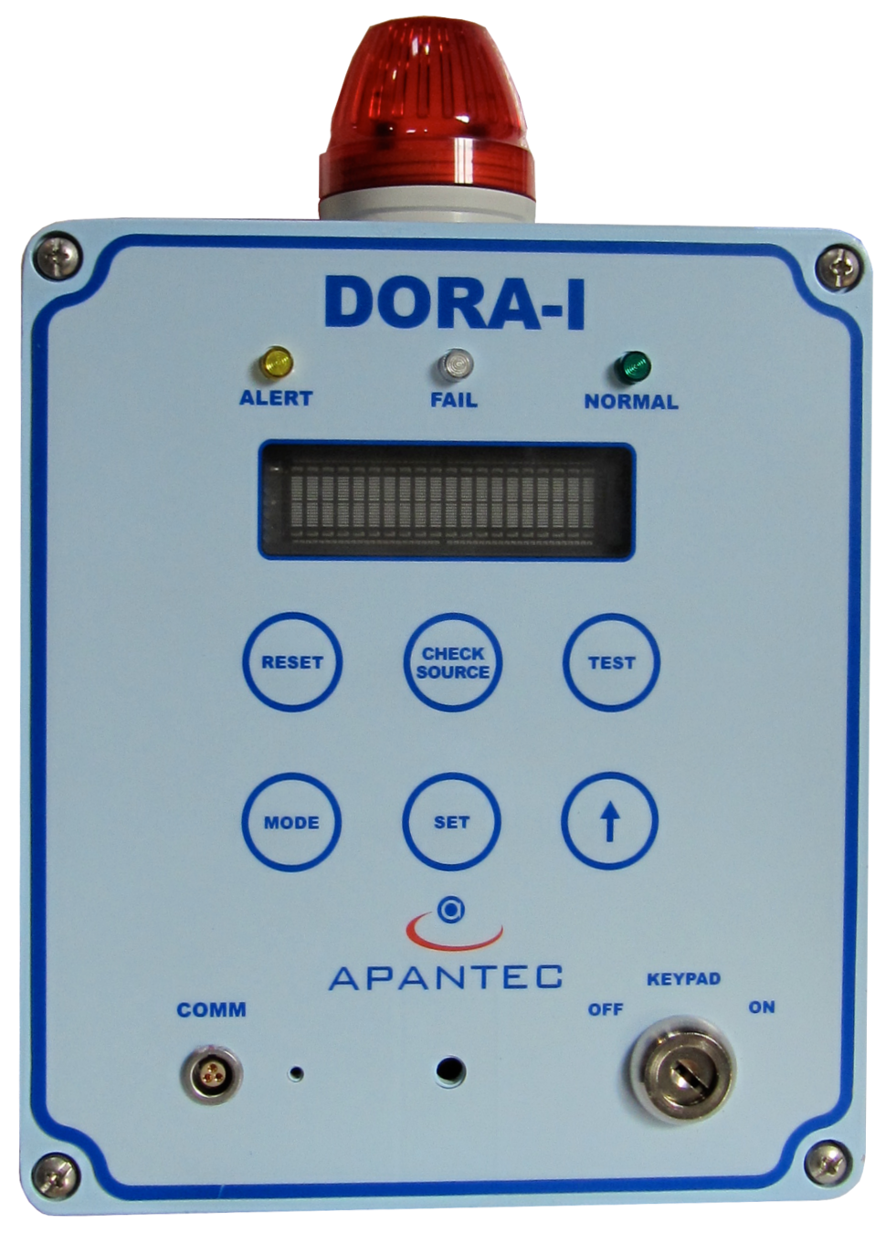
The DORA-I Series Radiological Activity Module is a single-board, low-power, ARM-controlled digital ratemeter that powers, operates, and monitors various APANTEC smart radiation detectors. The DORA-I is wall-mounted and can be installed on any vertical surface.
The DORA-I provides isolated relay closures, an isolated 4–20 mA current-loop output, isolated RS232/485 serial communications, and 10/100Base-T Ethernet.
It can operate with APANTEC area-monitor detectors and process-monitor preamplifiers and detectors. It can also be equipped with an internal GM detector and an optional check source. With either detector type, the ratemeter provides all detector power and control signals required for operation. Area-monitor detectors are designed for area detection of gamma or neutron radiation; process-monitor detectors are designed to be mounted in fluid or gas flow streams such as liquid piping, ventilation ducts, and stacks.
User-Interface Features
- 2-row × 20-character vacuum fluorescent display
- Six-position membrane switch panel
- Three-position key switch
- Four alarm indicators
Control and Communication Circuitry
- Control and counting circuitry for two smart-detector channels
- Voltage or current outputs (0–10 VDC or 4–20 mA)
- Communication ports (RS232C, RS485, Ethernet)
- Digital outputs
- Real-time calendar and clock
The DORA-I operates from 30–70 VDC Power-over-Ethernet or +24 VDC supplied by an AC-to-DC converter. The converter accepts universal AC input from 90 to 260 VAC, 47 to 63 Hz, single phase. The power supply is UL- and CE-certified and filtered against dropouts, voltage variations, surges, and spikes. Critical operating parameters are stored in non-volatile EEPROM so the system recovers from power outages without operator intervention, and historical data is retained in non-volatile memory. Operating parameters are field-configurable, supporting a common platform across multi-function channel and display configurations.
DORA-I Specifications
| Housing | NEMA 12 (IP 56) wall mount |
| Weight | 8 lb (3.6 kg) |
| Operating Temperature | 14 to 122 °F (−10 to 50 °C) |
| Operating Humidity | 0–95% RH, non-condensing |
| Input Power | Power-over-Ethernet, 30–70 VDC; (optional) 24 VDC |
| Maximum Input Current | 0.50 A |
| Detector Interface | Power, control, and counting for two detector channels (one internal, one external). Compatible with APANTEC smart detectors. |
| Internal Detector | GM tube with check source (optional) |
| External Detector | Compatible with neutron, GM, or ion chamber detectors |
| User Interface | Six-position keypad; three-position key switch (ON, OFF, KEYPAD lock-out); 2 × 20-character vacuum fluorescent display |
| Processor | NXP LPC2388 ARM-7 microcontroller, real-time applications |
| Alarm Indicators | Red: HIGH Amber: ALERT White: FAIL Green: NORMAL |
| Outputs | Digital: (1) RS232/485 and (2) TCP/IP Ethernet Analog: (1) 0–10 VDC or (1) 4–20 mADC isolated Two DPDT relays for FAIL, ALERT, HIGH, and other alarms or controls (programmed as required) |
| Communications | MODBUS |
| Displays | Dose rate, alert and high alarms, power-on indicator |
| Keypad Functions | Measurement-range selection; setpoint adjustment; input-power selection; stored-data access; local reset of warn/high alarms |
| Security | Key switch |
| Remote Controls | Alarm setpoints; reading radiation data; alarm acknowledge; forced alarm activation; reading internal diagnostic features; alarm trip times |
| Audio & Visual Displays | Flashing or steady, with programmable duty cycle for flashing |
Samplers and Pumping Systems
LS44 Liquid Sampler
The LS44 liquid sampler is provided for offline monitoring of liquid samples. The sampler is shielded with up to four inches of lead in a 4π configuration.
A drywell within the detector shield provides repeatable geometry for the scintillation detector while serving as a pressure boundary. The sample chamber is arranged for self-cleaning action to limit buildup of crud and contamination, and the liner is easily decontaminated when needed to preserve original sensitivity. An external riser pipe and self-venting sample chamber ensure no voids in the sample volume, supporting accurate concentration measurement.
The sampler bowl is highly polished stainless steel, with all wetted surfaces fabricated from corrosion-resistant stainless steel. The LS44 operates at liquid pressures up to 150 psig. Standard process connections are 150-RF flanges, with NPT optionally available.
LS44 Specifications
| Sampler Volume | 5.8 liters |
| Lead Thickness | 4 inches |
| Maximum Pressure | 150 psig (hydrostatic tested to 225 psig) |
| Weight | ~1,450 lb (~658 kg) |
| Exterior | Painted cold-rolled steel |
Low-Profile System Skid and Liquid Pumping System
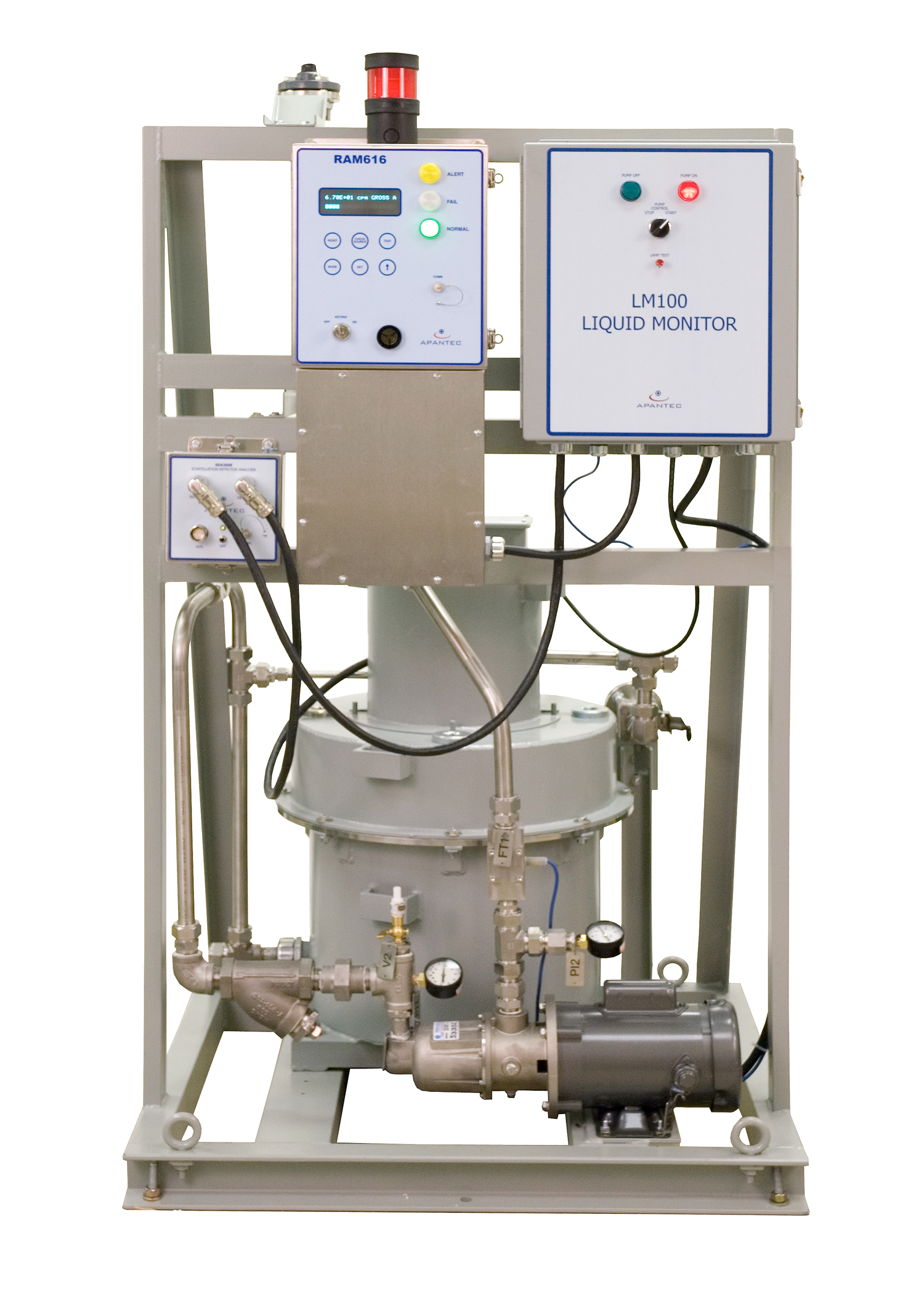
The liquid monitoring system is built on a single open-frame skid suitable for floor mounting. Lifting rings and forklift access are provided for movement to the monitoring location. The system includes a liquid pumping system capable of generating in excess of 20 GPM with a head lift of more than 16 feet. The pump is a centrifugal type, close-coupled to a ¾-HP electric motor. A basket strainer upstream of the pump suction removes large entrained material from the liquid sample to protect the pump. Local ON/OFF pump controls are provided on the skid; remote pump operation is optional. A flow indicator and flow control valve set the desired flow rate through the monitoring system. Fittings and valves for purging the liquid sampler are also available.
IS4X Inline Sampler
The IS4X fluid sampler is an inline shielded unit providing four inches of lead shielding around the pipe to be monitored and the detector. A drywell inside the sampler provides repeatable measurement geometry. The IS4X model number is based on the pipe size — the IS4 sampler is designed for pipe sizes 2 inches and larger. When used on pipe sizes 4 inches or smaller, the IS4X expands the sample volume to provide a minimum of five liters of sensitive volume.
Sampler Model Numbers
- 2-inch pipe — Model IS42
- 4-inch pipe — Model IS44
- 6-inch pipe — Model IS46
- 8-inch pipe — Model IS48
OS4A Online Sampler
The OS4A Online Sampler is an adjacent-to-line shielded unit providing four inches of lead shielding around the pipe to be monitored and the detector. A drywell inside the sampler gives the detector a repeatable measurement geometry. The OS4A is a split-shield design that bolts to the exterior of the pipe being monitored, and is intended for pipe sizes 4 inches and larger.
OS4A Specifications
| Sampler | 150 lb–rated pressure |
| Shielding | 4" lead in a 3π geometry |
| Flow Rate | Determined by existing flow rate |
| Sampler Weight | 600 lb nominal |
| Process Fluid Temperature | 30 to 130 °F (−1.1 to 54.4 °C); high-temperature systems available |
AS43F Fixed-Filter Particulate or Iodine Sampler
The AS43F sampler is provided for monitoring of particulate and/or iodine activity. It is shielded with up to three inches of lead in a 4π configuration. A detector mount within the shield gives a repeatable geometry for the scintillation detector and serves as a pressure boundary. The AS43F is an easy-to-use design that uses a fixed filter holder for collection of airborne radioactive particles and/or iodines. The filter holder accepts industry-standard 47 mm filter paper as well as a TEDA or silver zeolite cartridge for capture of iodines. When used for particulate monitoring only, the cartridge is replaced by a backing screen to support the filter paper.
When installed within the sampler, the scintillation detector sits in close proximity to the deposited material for maximum sensitivity. The sampler is built from painted cold-rolled steel, with corrosion-resistant stainless steel on wetted surfaces.
AS34M Moving-Filter Particulate or Iodine Sampler
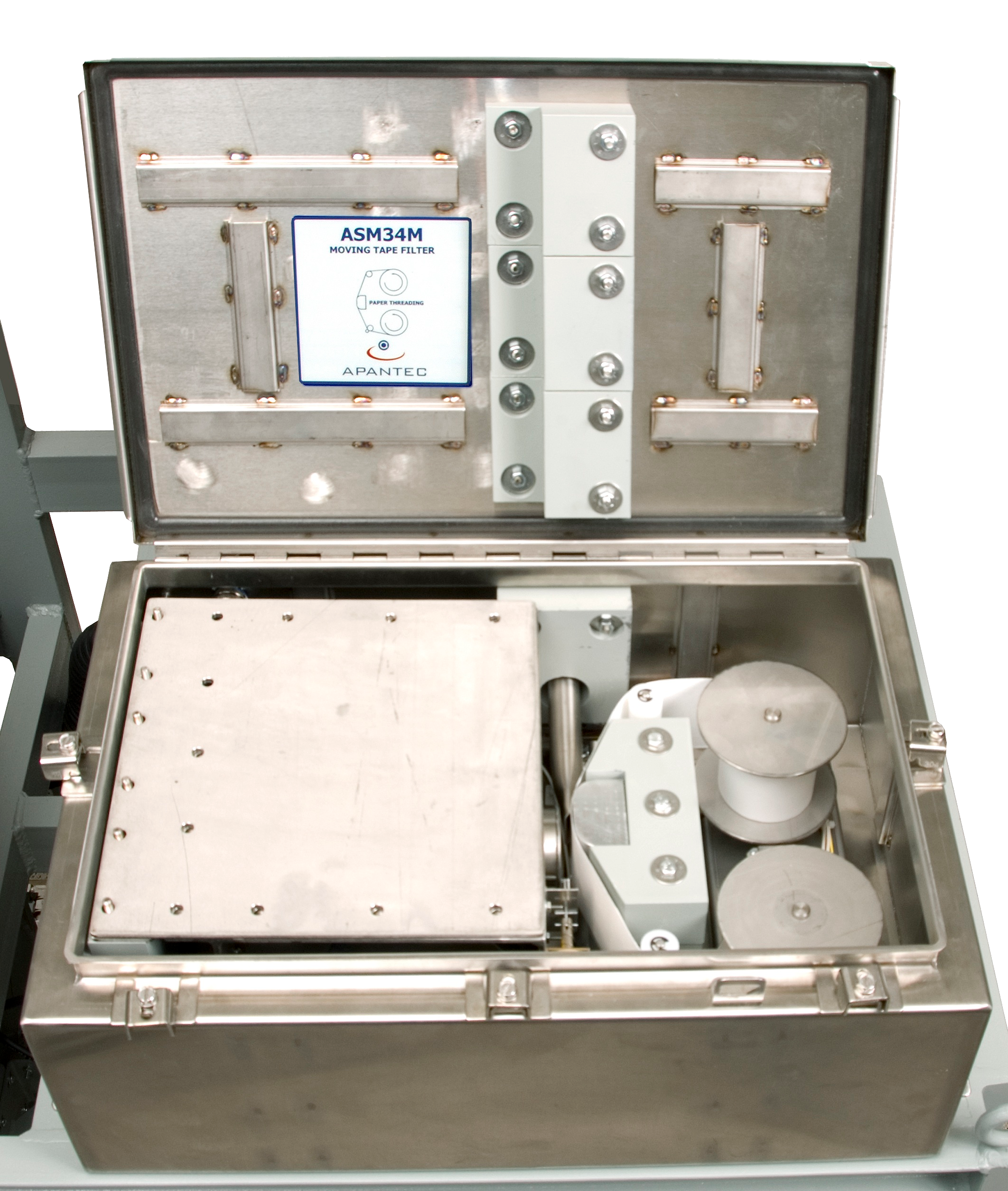
The AS34M sampler is provided for monitoring of particulate and/or iodine activity. It is shielded with up to three inches of lead for attenuation of gamma background. A detector mount within the shield gives a repeatable geometry for the scintillation detector and serves as a pressure boundary. The AS34M uses a moving-filter design for collection of airborne radioactive particles and/or iodines. The sampler accepts filter media in roll form — either standard filter media for particulate collection or charcoal-impregnated media for combined particulate and iodine collection. When installed within the sampler, the scintillation detector sits in close proximity to the deposited material for maximum sensitivity. Wetted surfaces are corrosion-resistant stainless steel; standard process connections are 1" NPT.
Moving-Filter Vacuum / Sampling Specifications
| Filter Paper | Particulate: 3"-wide roll, equivalent to H&V LB5211 |
| Iodine | TEDA-impregnated Type 72; 99% retention of 0.3 µm or larger particles & iodine at 1 SCFM (30 LPM) |
| Vacuum Pump | Progressive-cavity carbon vane, diaphragm, or metal bellows; 5 inHg at 1 SCFM flow |
| Flow Rate | 0–1 SCFM (0–30 LPM) rotameter standard; optional thermal mass flow measurement (±15% accuracy) |
| Flow Totalizer | Continuous totalization until reset |
| Power | 220 VAC or 120 VAC, 50/60 Hz, single phase |
| Outputs | Low-flow alarms; DPDT relay, 5 A, 120 VAC rated; visual display on RM1W digital display |
GS45 Noble Gas Sampler
The APANTEC GS45 Noble Gas Sampler is provided for continuous monitoring of noble gas activity. It is shielded with four inches of lead in a 4π configuration. A well within the detector shield provides repeatable geometry and exposes the sensitive end of the detector to the gaseous activity. The sample volume provides sufficient gas volume to meet required sensitivity, with a nominal volume of 5 liters. Sample conditions are automatically corrected to standard pressure using a vacuum transducer at the sampler-volume inlet. The sampler is built from steel with corrosion-resistant stainless steel on wetted surfaces, and is designed for vacuum operation up to 5 psig. Process connections use dual-ferrule compression fittings on 300-series stainless-steel seamless tubing.
Features
- Dual local/remote ratemeter utilization
- Gain-stabilized scintillation detectors
- Extended calibration cycles
- Particulate and noble gas detectors on the same skid
- Common flow controllers and vacuum pumps
- Improved moving-paper drive
- Vacuum pump improvements using bypass lines
- Power supplies with reduced heat loading
- Modular components
- Reduced MTBF with self-diagnostics
- Noise / spiking / electromagnetic-interference reduction
- EMI/RFI compliance to EPRI standards
Low-Profile / Vacuum Pumping System
The air monitoring system is built on a single open-frame skid suitable for floor mounting. Lifting rings and forklift access are provided for movement to the monitoring location. The system includes a vacuum pumping system capable of generating in excess of 1 SCFM. The pump is a carbon-vane progressive-cavity or metal-bellows pump with an integral fractional-horsepower motor. Local ON/OFF pump controls are on the skid; remote pump operation is optional. A flow indicator and flow control valve set the desired flow rate.
Fixed-Filter Vacuum / Sampling Specifications
| Filter Paper | Particulate: 47 mm to 57 mm Iodine: TEDA-impregnated Type 72, 2.25 in. dia. (57.1 mm); 99% retention of 0.3 µm or larger particles and iodine at 1 SCFM (30 LPM) |
| Vacuum Pump | Progressive-cavity carbon vane, diaphragm, or metal bellows; 5 inHg at 1 SCFM flow |
| Flow Rate | 0–1 SCFM (0–30 LPM) rotameter standard; optional thermal mass flow measurement (±15% accuracy) |
| Flow Totalizer | Continuous totalization until reset |
| Power | 220 VAC or 120 VAC, 50/60 Hz, single phase |
| Outputs | Low-flow alarms; DPDT relay, 5 A, 120 VAC rated; visual display on RM1W digital display |
Software
DORIS — Display Of Radiological Information Software
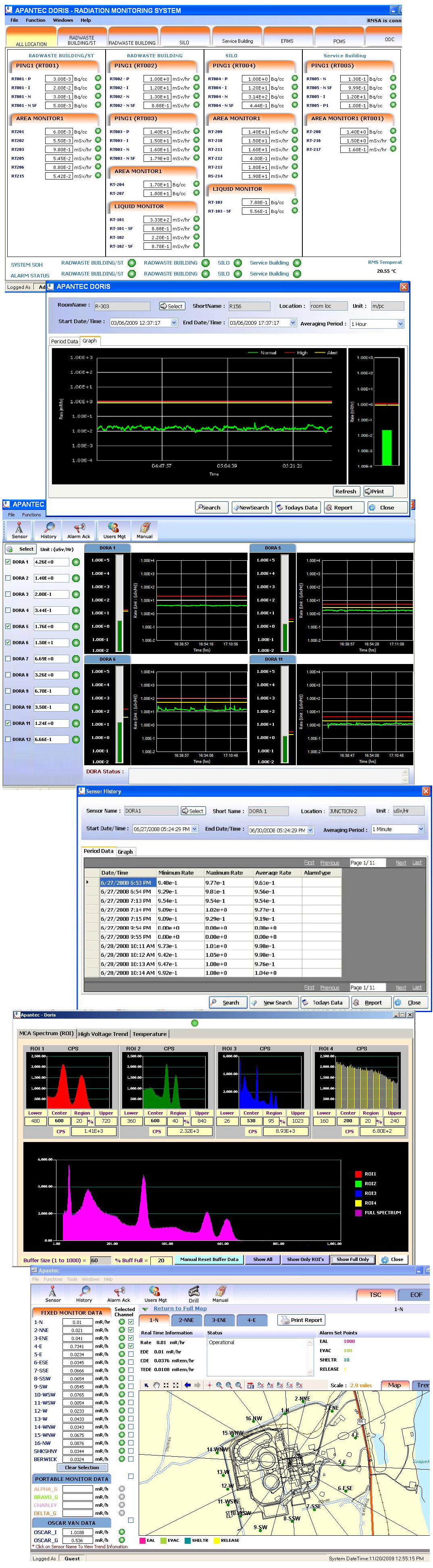
APANTEC offers a comprehensive tracking and trending program called DORIS — Display Of Radiological Information Software. DORIS provides real-time data reporting and control through a user-friendly graphics interface. Data is collected, analyzed, displayed, and recorded in real time, with alarms posted for operator notification. DORIS is compatible with the RM1-series DCU or the DORIS hardware platform, and displays both acquired radiological and meteorological data. It communicates with each monitoring channel using either serial or Ethernet communications.
DORIS Functions
- Collecting, converting, storing, integrating, and analyzing data from all monitors
- Detecting, annunciating, and storing alarm conditions
- Remote check source and calibration
- Providing current and historical displays of any channel on operator request
- Generating system and graphic displays
- On-line database and display generation/modification capability
- On-line diagnostic displays
- Report and event management
- Custom integrations with geographical maps and third-party tools
DORIS Real-Time Display and Indicators
- Current readout of background or gaseous activity
- Detector information (type, SCA setpoints, etc.)
- High / Alert / Fail alarm status
- Detector status (fail, normal, etc.)
- Keypad status, State of Health (SOH)
- Trend information
- Graphic representation of trending data
Maintenance, Repair, and Refurbishment
APANTEC offers full preventive maintenance, repair, and refurbishment programs for nuclear generating stations using detectors, preamplifiers, and remote/local alarm indicators originally supplied by Nuclear Research Corporation and Canberra.
APANTEC has dedicated repair and test facilities as part of its manufacturing and test departments to accommodate fabrication, repair, and testing of all equipment. We also offer free phone support for troubleshooting questions.
Our factory services include a full range of options — equipment repair, calibration, preventive maintenance, and parts ordering. All equipment is serviced by highly skilled technicians using automated test equipment and instruments calibrated to NIST-traceable standards. Calibration certificates compliant with your quality program are available upon request.
APANTEC repairs and calibrates Nuclear Research Corporation and Canberra Industries electronics back to factory condition. All instruments are returned with a one-year factory warranty.
Service for Recommended On- and Off-Site Spare Parts
APANTEC offers a one-time engineering service to determine the configuration of all NRC- and CI-supplied radiation monitoring system spare parts. The service includes a one-day on-site evaluation of equipment and documentation. At the conclusion of the engineering study, APANTEC delivers a comprehensive list of recommended spare parts — complete with document control numbers and configuration information for each channel — along with recommendations for the quantity and type of spare parts to maintain on-site (as ready/critical spares) and at APANTEC (for off-site support and hot standby).
Annual Service and Support Contract
APANTEC is committed to quality service following the delivery and installation of our instruments. We offer full logistics support throughout the life of our equipment, plus complete customer service including engineering, startup, and training.
Our Service and Support Contract offers:
- On-site maintenance agreements for users who require the highest level of service
- Extended warranty agreements for customers who want rapid response and a fixed-fee repair service
- Calibrated and fully tested spare parts at our facility for emergency replacements
- Standard return-to-factory service options (repair and calibration)
- Optional priority repair service for urgent situations
- Startup assistance
Upgrades
APANTEC offers several upgrade paths for existing customers using Nuclear Research Corporation or Canberra radiation monitoring instruments. Instruments can be refurbished to factory condition, upgraded by replacing the electronics with the latest-generation designs, or replaced as a complete form-fit-and-function unit. This methodology extends the service life of the original equipment by providing a readily available source of spare parts, replacement modules, and ongoing service.